H. P. Friedrichs (AC7ZL) Homepage


Radio Room
Building the "Sanfordyne" Receiver
Introduction
Anyone who knows anything about basic radio has at least heard the term "heterodyne." If antique radio is your interest, you are likely to be familiar with the terms "neutrodyne" or "regenodyne." A casual review of radio magazines from the 1920's will reveal numerous lesser-known phrases like "strobodyne," "metrodyne," "tropodyne," "peridyne," and even "fremodyne." It seems that the formula for a successful "high-tech" trade name in that era was to concoct some prefix and then append "dyne" to the end of it.
Now fast-forward about a half a century. In January of 1972, NBC Television aired the first episode of their hit sitcom Sanford and Son. The show's plot was based upon the misadventures of Fred G. Sanford, an elderly junk dealer, and his adult son Lamont. The old man was grumpy, cantankerous, and scheming, though somewhere in the midst of all that he seemed to have a good heart. The son, often referred to as "big dummy," was himself a decent fellow. He generally wanted to do the right thing, but he always found himself entangled in his father's shenanigans. The end result was plenty of laughs and a great deal of entertainment.
In homage both to radio's "dyne" tradition, and to the setting and characters of Sanford and Son, I affectionately refer to this receiver project as the "Sanfordyne." The reasoning behind this becomes more readily apparent as one recognizes the nature and source of the materials used in its construction.
My intent in building the Sanfordyne was not about the creation of a high-performance rig or the subsequent publication of detailed plans and schematics. The parts and materials I used truly were junk, and it goes without saying that there is a certain randomness associated with trying to build things from cast-offs. The real purpose of the Sanfordyne is to show that a functional receiver can often be crafted from the lowest grade of scrap material.
Those with limited technical backgrounds and those of limited means will appreciate that the Sanfordyne was built through an empirical process, without the benefit of any design calculations, or of any test equipment beyond a simple voltmeter. At the very least, a scan through this text and a glance at the images here may provide useful ideas for implementation in your own Sanfordyne-like project.
Before I proceed with further explanation, please hear, understand, and embrace the following warning: Tube circuitry requires potentially fatal voltages to operate. When this equipment is plugged into, and powered by utility outlets, there are additional potential shock and fire hazards. If you are unqualified to deal with these types of energy sources, don't mess with them. Find someone qualified to mentor or assist you, or simply leave the construction of these types of devices to others, and enjoy the rest of this article for its academic value.
Circuit Topology
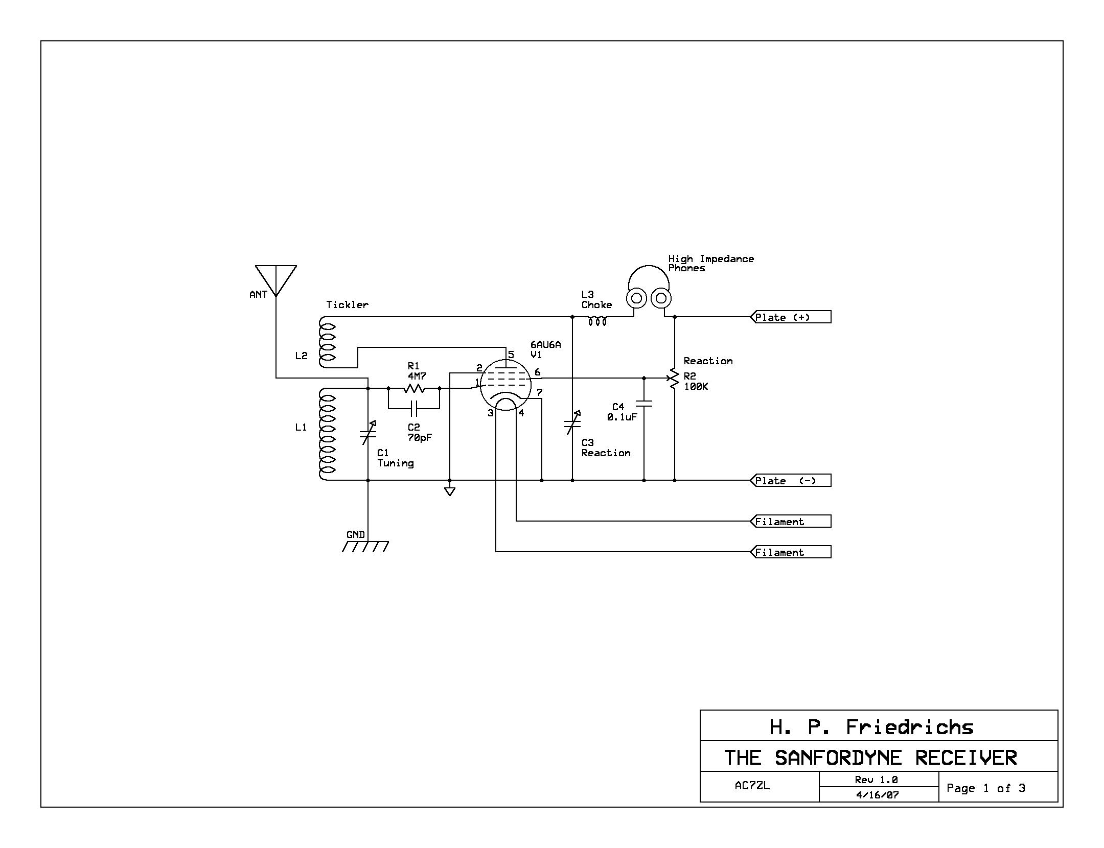
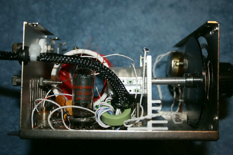
The circuit topology used in the Sanfordyne is both ancient and well known, and is depicted here. Amplification in this circuit is provided by a 6AU6A miniature glass pentode (vacuum tube.) The 6AU6A (and tube socket) used in my Sanfordyne was salvaged from a trashed oscilloscope. Believe it or not, 6AU6As are still cheap and readily available from tube dealers on the Internet, so if you can't find one of these tubes, you can certainly buy one. Note, however, that there is nothing critical in the design of this radio that would prevent other types of pentodes from being used.
http://datasheets.electron-tube.net is a great place to find datasheets for tubes you might have in a junkbox someplace. Remember, the Sanfordyne philosophy is to use what you have.
Tuning is accomplished by setting up a resonance condition in coil L1 and variable capacitor C1. Ordinarily, in designing a receiver, one has a span of target frequencies in mind. A simple equation relates resonant frequency to the product of the coil's inductance and the capacitor's capacitance value. Having a target frequency in mind, and having chosen an available capacitor value, one can quickly compute the required inductance value needed to achieve resonance.
In the case of the Sanfordyne, I wanted to build a radio to pick up the A.M. broadcast band. The variable capacitor I had scrounged up had an unknown value. (I could have measured it, but for the sake of the Sanfordyne concept, I elected not to.) This means that the value of an appropriate coil would have to be determined experimentally. More on this later.
Capacitor C2 and resistor R1 form what is known as a "grid-leak bias." The grid-leak bias is a clever way to "set up" the tube for proper electrical operation. The Sanfordyne will function with a wide range of grid-leak component values, but after tinkering with rig for awhile, I settled on 4.7 megohms for the resistor, and about 70 picofarads for the capacitance.
A second coil, L2, is sometimes referred to as a "tickler" coil. Signals amplified by the tube are sent to the tickler, which magnetically couples some of the energy back to the input of the tube (through L1.) This electrical feedback encourages the tube to re-amplify the same signal over and over again. This trick, a process is known as "regeneration," results in a large amount of amplification, and makes the radio very sensitive to weak signals.
Too much regeneration is not a good thing. It can lead to the production of a piercing shriek in your headphones, distortion of the received audio, and reduced sensitivity. The amount of regeneration must be carefully controlled, "throttled" if you will. In the Sanfordyne, throttling is accomplished in two ways.
First, capacitor C3 limits regeneration by controlling the amount of energy that the tickler can feed back into L1. In my Sanfordyne, C3 is a small, adjustable "trimmer" capacitor, salvaged from some unknown junk. Its value is in the 100-picofarad range. It's intended as a coarse adjustment, to be tweaked when the radio is first assembled and then forgotten.
Fine control of regeneration is accomplished with a potentiometer, R2, which is mounted on the front panel of the receiver. R2 is set up as a voltage divider, sampling some fraction of the supply voltage and applying that to the tube's screen grid. The higher the screen grid voltage, the more gain the tube provides, which results in more regeneration. Conversely, if the screen grid voltage is reduced, the tube produces less gain. This means that R2, typically referred to as a "reaction" control, can also be used as a volume control. Capacitor C4 is used to promote circuit stability by keeping the screen voltage noise-free.
This circuit requires the use of high-impedance headphones. Vintage magnetic headphones are my first choice, but there are other options. Low-impedance headphones can be used if a matching transformer is inserted between the radio and the headphones. A third option is to use "crystal" headphones, though such headsets will have to be shunted with a resistor in order to provide a D.C. return path for the tube's plate circuit. I recently wrote an article for the Xtal Set Society that describes the use of brass piezo disks as transducer elements in a set of homebrew high-impedance headphones. Join the XSS and get yourself on the mailing list.
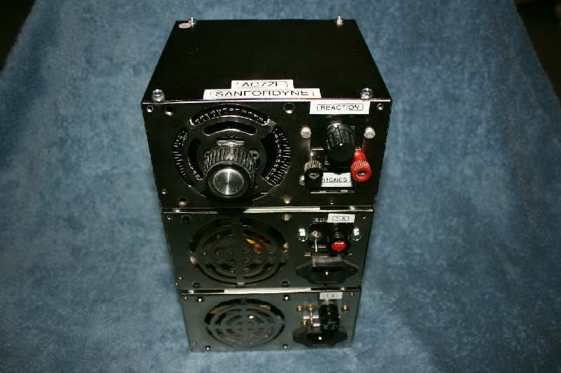
The Sanfordyne system actually consists of three pieces or modules. The first is the receiver itself. The other two modules represent low and high voltage power supplies, for the purposes of energizing the filament and plate circuits, respectively.
Receiver Mechanical Details
Personal computers rank among the most remarkable developments of the last century. At the same time, the rapid pace of developing computer technology and the throw-away nature of contemporary computer designs results in landfills filled with horrific mountains of discarded (and toxic) computer hardware.
Central to the Sanfordyne project is the idea that where there is junk, there is opportunity. The steel cabinets used in the Sanfordyne are all recycled PC power supply enclosures. Anyone who services their own computer is likely to have one or more of these lying about. If not, a visit to any local computer repair business will probably get you more dead supplies than you'd know what to do with. If you doubt the value in this effort, check some of the online electronics supply houses on the price of a comparable metal enclosure. You'd be amazed at the amount of money you can save by recycling.
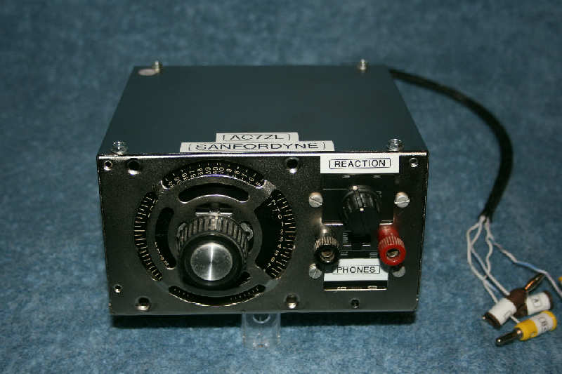
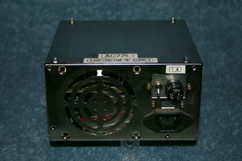
In the case of the receiver module, I started with a dead supply and gutted it, leaving only the steel shell. Large holes had been punched into the cabinet to accommodate the IEC power connectors and voltage selector switch. I covered these openings from the inside of the cabinet with an aluminum plate. This plate, incidentally, was salvaged from the slide-rule station-indicator of a scrapped portable radio. I drilled holes into this plate to accommodate the receiver's reaction control and to anchor the binding posts through which the radio's headphones are attached.
One of clever ideas to emerge from this project, even if I do say so myself, is the tuning mechanism. The mechanism is attractive, functional, and addresses an annoying problem associated with the use of some variable (tuning) capacitors.
While many, perhaps most, of the tuning capacitors I've run across have 1/4-inch round shafts, a lot of the miniature capacitors used in later gear do not. In fact, the latter tend to have stubby shafts with two flats. It's next to impossible to attach a standard knob to them, and an ordinary shaft coupler or extension is of no use.
To solve this problem, I dug up a 1/4-inch aluminum standoff for use as a custom tuning shaft extender. Using a metal file, I notched one end of the standoff until it fit perfectly onto the end of my tuning capacitor's shaft. Note that the extension is not fixed to the variable capacitor shaft, it merely engages it. I recycled one of the PC power supply's aluminum heat sinks and used it as a mounting bracket for the capacitor. I drilled a hole into the front of the cabinet, inserted my shaft extension, and engaged it with the capacitor. So far so good.
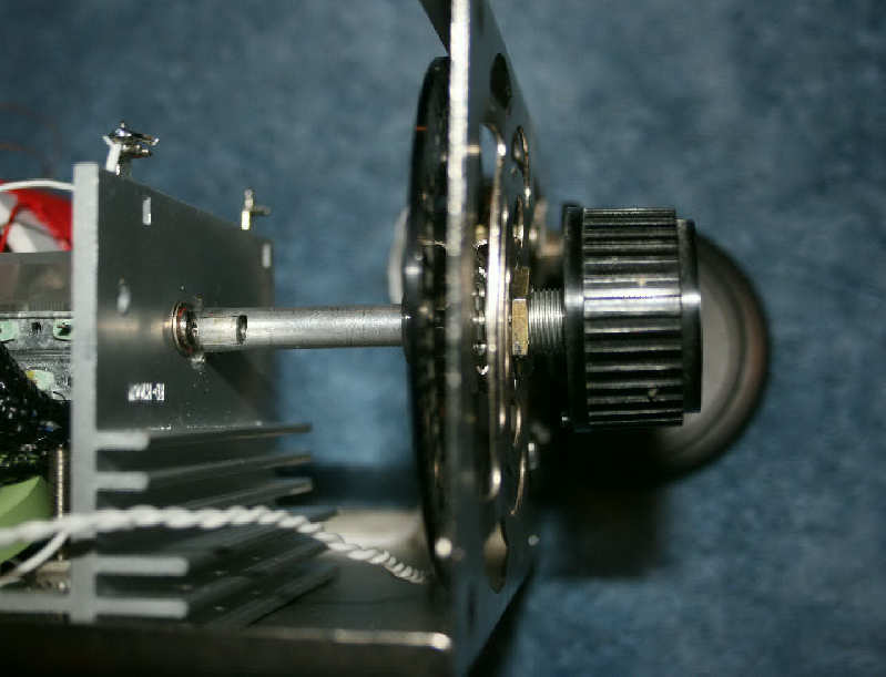
The shaft needed a bearing where it passes through the wall of the cabinet. I found a burned-out potentiometer and took it apart to extract the threaded shaft bushing. The bushing was installed in the wall of the cabinet with an appropriate "volume control" nut. My homebrew shaft extension rotates smoothly and easily inside of this bearing.
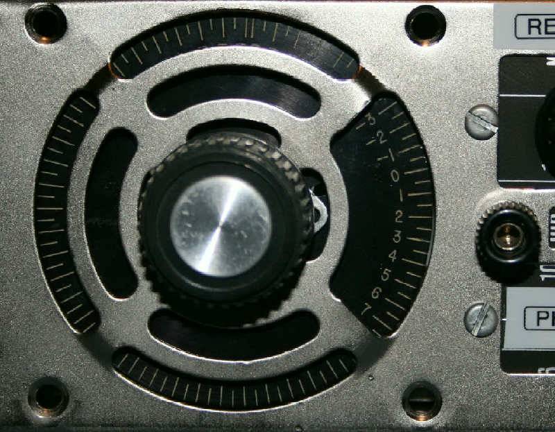
The dial indicator is a disk of aluminum salvaged from some more electronic junk. Mine happens to be black, with white, numbered, graduations around its outer edge. The dial face from an old pressure gauge, rpm indicator, or clock face would probably work just as well. My dial had a hub, making it easy to attach to the shaft. In a pinch, one could crush an old Bakelite instrument knob and extract the brass collar and set screw inside. Epoxy the collar to the dial, and then affix the assembly to the shaft with the set screw.
Since the dial is affixed to the shaft, the shaft can't move axially, which forces the notched end to remain engaged with the capacitor. It may be necessary to put a washer or two between the dial face and the bearing to secure sufficient clearance to allow the dial to spin freely.
I located my tuning mechanism so that the indicator dial would be positioned behind the perforated "grill" where the supply's fan had once resided. The slots punched in the metal provide "windows" through which the numbers and graduations can be seen. I wanted better access to the markings on the dial, so I used some tin snips and a nibbling tool to remove a pie-shaped sector of the grill.
The tuning mechanism is completed with the installation of a knob on the protruding end of the extension shaft.
Circuit Construction Details
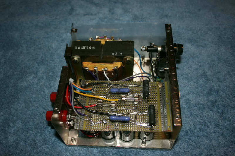
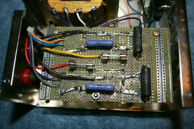
Regenerative radios work best when their internal wiring is as short and direct as possible. With this in mind, I created a "circuit board" with a piece of un-etched copper-clad circuit board and a Dremel (TM) grinding tool fitted with a tiny round-ball rasp. In the center of the board, I created seven pie-shaped copper "islands" to which the tube socket was soldered. I also created a number of rectangular islands surrounding the tube, to provide soldering pads for wires and some of the electronic components.
The circuit board was fastened to the floor of the Sanfordyne's housing with two 6-32 screws and nuts. One of these screws passes through a copper island, which is used as a ground. This causes the entire enclosure to be referenced to ground, including the "common" end of the plate supply.
Among the useful parts that can be extracted from a dead PC power supply are the toroids used for filtering. If you remove the wire wound upon them, they can be rewound as necessary and used for other purposes. The coil appearing as L3 in the receiver schematic, for example, is one such toroid. It was salvaged from a dead supply, denuded of the magnet wire that was on it, and then rewound with a few feet of fine hookup wire. It functions as a choke to keep radio frequency currents out of the headphone circuitry. Toroids were also installed on the filament and plate supply lines to keep them free of RF.
Tuning Coil and "Tickler" Concerns
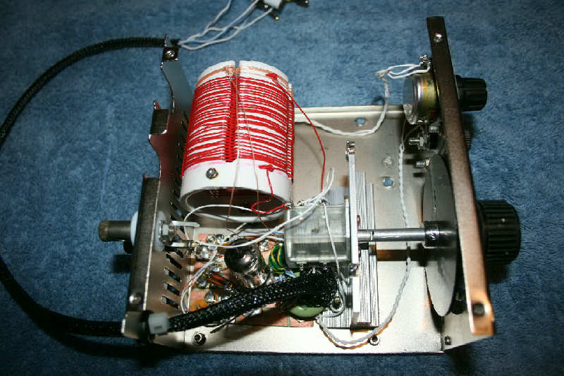
The tuning coil, L1, was wound upon a 1-1/4" PVC plumbing coupler. I originally wound this coil with enameled magnet wire, in a single, flat, layer. This resulted in tuning difficulties, which I attributed to parasitic capacitance between the windings.
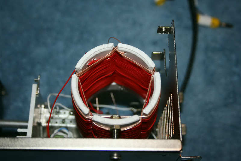
To combat this, I rewound the coil in a sort of "basket-weave" fashion. I cut slots into the coil form to create five plastic fingers. The coil wire was woven around these fingers, first over, then under, then over again. I eventually stopped when the coil reached 29 turns.
The tickler coil, L2, is wound in similar fashion, adjacent to L1, but consists of only 4 turns.
Earlier, I alluded to an "empirical' method of coil design. Assuming that the rest of the radio circuitry is complete and functional, the method is this:
Start by winding L1 with "a bunch" of turns. How much is "a bunch?" A few dozen, perhaps, it doesn't really matter. Short-circuit coil L2 with a short piece of wire to disable it. Hook up an antenna, a ground, and headphones. Turn the reaction control all the way up (maximum voltage at pin 6 of the tube.) Power up the Sanfordyne and listen. Adjust C1 up and down. Listen some more. If you're unlucky, and hear nothing, remove a few turns of wire from L1, and try again. Repeat this process.
If you never hear any stations, no matter how much wire you remove from L1, wind it back to the way you had it originally, and repeat the trial-and-error process. This time, however, you want to add turns from trial to trial.
Assuming that you constructed the rest of the circuit properly, you'll eventually hear an A.M. broadcast. Listen for a call sign or try to identify the program you're hearing. Fetch another A.M. radio, a factory-built set, turn it on, and sweep the tuner up and down until you've found the station you were listening to on the Sanfordyne. The dial position will you give you an idea how to proceed.
If you want the Sanfordyne's tuner to favor lower frequencies, add windings to L1. If you want the tuner to favor higher frequencies, remove a few turns from L1. It's that simple.
It is possible that C1 will not allow you to span the entire A.M. broadcast band, even with a properly-designed coil. If this is a problem, you might have to find another variable capacitor. If C1 is a multi-section capacitor, composed of two or more variable capacitors on the same shaft, try tying two or more sections together. You may have to redesign your coil, but this should result in a greater tuning range.
Once you've got L1 and C1 working together the way you'd like, remove the short circuit from L2. You should hear a loud hiss or shriek in the headphones. Back down the reaction control until that noise just ceases. In this state, the receiver is most sensitive, and you'll be surprised at how loud some the incoming stations will be. Depending upon your antenna, it may be necessary to readjust the reaction control as you tune around the dial.
If you never get the hiss or shriek, no matter what you do, trying increasing the value of C3. If that doesn't help, your ticker coil may be phased incorrectly. Disconnect L2 from the circuit, swap the two wires, and reconnect it.
Power Supplies
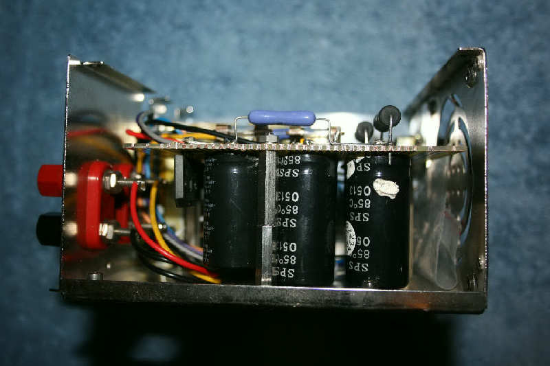
As salvage items, PC power supplies are useful sources of a number of pieces and parts, beyond the utility of their enclosures. For example, every switching supply I've ever opened contained a bridge rectifier and one or more large electrolytic capacitors in the 200 to 400-volt range. If the bridge is good and the capacitors haven't gone stale, these parts can be used to build high voltage supplies like those used to power the Sanfordyne's plate circuitry.
PC power supplies contain other useful parts, too. These might include power resistors, inductors, fuses and fuse clips, regulator IC's, and connectors, like the one that mates with standard IEC computer power cords.
The Sanfordyne requires two sources of power, a low-voltage source to light the filament in the tube, and a high-voltage source to power the plate circuitry. Let me discuss the construction of the plate, or "B" supply first.
The "B" supply, like the Sanfordyne receiver itself, was built in a gutted PC power supply housing. The schematic can be viewed here.
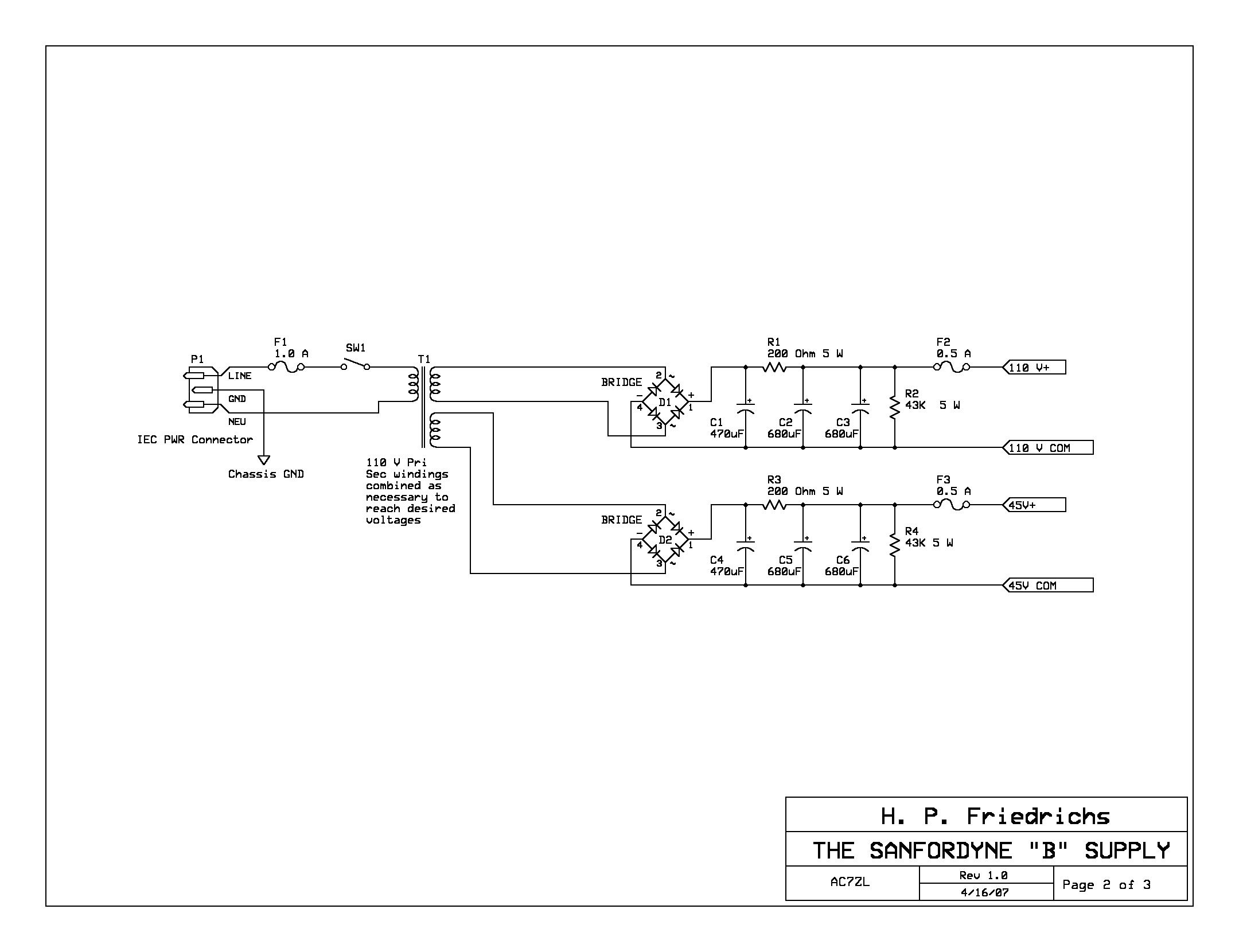
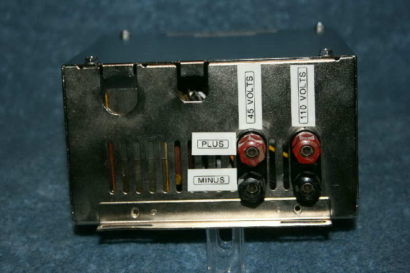
The first order of business in the construction of this supply is to locate a suitable transformer. One can purchase "plate" transformers, but they can be expensive. Some transformers, found in junked equipment, are wound with more than one output winding. If no single winding gives you the voltages you want, you always have the option of combining two windings in series to give you a voltage equal to the sum of the two. The transformer used in the Sanfordyne's "B" supply has multiple output windings, enough so that I was able to combine coils to generate two independent voltages, both 45 and 100 volts.
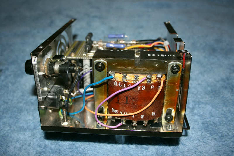
Remember that when combining transformer output windings, phase matters. If you connect two coils in series and find that the total voltage drops instead of increases, you're probably not looking at the sum of the two voltages, but the difference. This means you have one of the coils connected backwards.
Whatever you do, resist the temptation to eliminate the transformer. Some old electronics books and magazines show receivers and similar projects powered directly from household mains. This is an invitation to injury and death. Don't do it.
The voltages produced by the transformer are AC voltages, the Sanfordyne's plate circuitry requires DC. The necessary conversion is done with a rectifier bridge, filter capacitors, and power resistors, all of which can be salvaged from PC power supplies and similar electronic junk. The 43-thousand-ohm resistors are "bleeders." They are there to make sure that the capacitors discharge fully when the supply has been turned off.
Note that the "B" supply is fused both at the supply side and at the output side. The input fuse offers some protection from fire. The output fuses offer some protection to the "B" supply in the event that the output is accidentally short-circuited.
The Sanfordyne "A" supply is a much simpler device. It consists of a scrap transformer that converts house current to 6.3 volts AC. The schematic can be viewed here. The 6AU6A tube used in the Sanfordyne has an indirectly-headed cathode, so it doesn't care whether the filament supply is AC or DC.
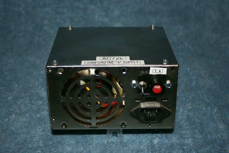
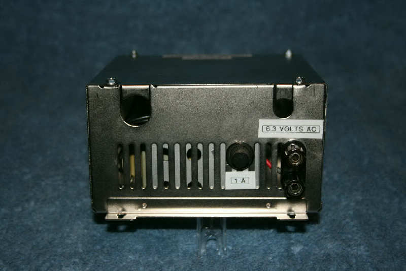
Like the "B" supply, and for the same reasons, the "A" supply is fused both at the input and output.
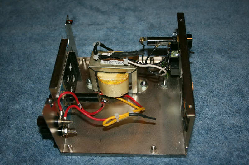
Note that all of the parts used in the Sanfordyne "A" and "B" supplies, including the power connectors, switches, fuse holders, capacitors, wire, transformers, rectifiers and banana jacks, were scrap items salvaged from discarded electronic junk.
Results and Impressions
Considering the relative simplicity of the circuit, and the materials from which it was constructed, the Sanfordyne is surprisingly sensitive. I've operated the receiver using as little as 45 volts on the plate, and it worked fine. Operating at 100 volts results in somewhat better performance.
The regeneration control R2 works smoothly, audio quality is good, and the radio is quite stable. There are no problems with hand capacity. This is no doubt due to the grounded metal enclosure and the use of toroids to suppress the leakage of RF currents.
The tuning circuit composed of L1 and C1 is unbuffered. This means that the tuning dial calibration is affected by the length and height of the antenna attached to the receiver. There's no point in marking the tuning dial with frequencies for specific stations, unless the radio will always be used with the same antenna. This idiosyncrasy can be annoying, though it can also be used to benefit. External coils and capacitors can be applied to the antenna terminal to influence and modify which frequencies the Sanfordyne will receive.
The variable capacitor I used does not allow for the tuning of the entire AM broadcast band. In retrospect, I could have replaced it with another, or better yet, made use of a tapped tuning coil instead of the fixed coil described. Another idea involves using plug-in coils.
I still have an extra PC power supply case left over. A neat idea might be to build a combination audio amplifier/speaker box to allow the Sanfordyne to be enjoyed without the use of headphones. I've got a 6AQ5 and an audio transformer lying around. A small permanent magnet speaker would fit nicely into the fan grill. Hmmm...
If you'd like to see plans for a nifty home made earpiece to go with this radio, click here.
Document Revision 1, xx/xx/xxxx
Document Revision 2, 04/26/2007