H. P. Friedrichs (AC7ZL) Homepage


Radio Room
Digging Dirt on Inductors: Homemade Magnetics from Black Sand
Introduction
If you're inclined to believe that every radio/electronics project begins with a catalog order from Digikey or Newark, then you are obviously not familiar with my books, my website, or my work. I think it fair to say that I have talken the "from scratch" construction ethic to places that not everyone thought was possible.
I've built and demonstrated homemade tubes, transistors, electromechanical amplifiers, variable capacitors and tuning coils, a variety of homebrew headphones (both piezo and electromagnetic), crystal detectors, and even carborundum-based LEDs, not to mention numerous projects made from recycled bits and pieces. That said, if I now claimed to have fabricated useful electrical and electronic components from the "dirt" in my backyard, you might none the less wonder if I'd finally fallen off the turnip truck. I can assure you, however, that I am quite serious.
In the early part
of 2020, I was invited to make a presentation at the first QSO
Today Virtual Hamfest. Something on the order of 15 thousand
persons are said to have attended, and some fraction of those people
found their way into my August 9, 2020 talk entitled: Digging
Dirt on Inductors: Experiments with Custom Magnetics Made from "Black
Sand."
I
Figure 1: My QSO Today Expo presentation cover slide
The premise of my talk is nearly as straight-forward as the title would imply. My curiosity about magnetite particles ("black sand") found in abundance in Arizona roads and washes, lead to a series of interesting experiments with some surprising conclusions.
My Paper, and How to Get Your Own Copy
In short, I was able to develop a process for binding those particles with resin, so as to permit the casting of a variety of interest magnetic structures including bars and toroids. I demonstrated electronic functionality with a sand-based AM receiving antenna, a "Joule Thief" circuit, and a FET RF oscillator--all based upon components cast from magnetite sand.
Experiments with home-made adjustable loop sticks and cast transformers lead to additional experiments employing the metal shavings produced by brake drum lathes. This improved my experimental transformers, and I was able to apply that material to a functional universal motor field and a built-from-scratch, half-kilowatt alternator.
Since a half-hour presentiation time slot necessarily limited the scope of my presentation, I took the trouble to put together a 65-page descriptive paper--really a short book--highlighting these experiments and much more. The paper provides additional background on what I did, how I did it, and what prompted the decisions I made. I was not shy about documenting any failures that occurred, either.
There is no point replicating the totality of the paper's content here, since you can download and review the paper for yourself by clicking THIS link.
Gallery
In the meantime, I invite you thumb through some of the images below. These represent some of my "black sand" projects. You might find them interesting. If you happen to replicate or improve upon what I've done, I'd be very interested in hearing from you.
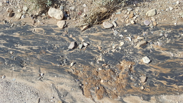
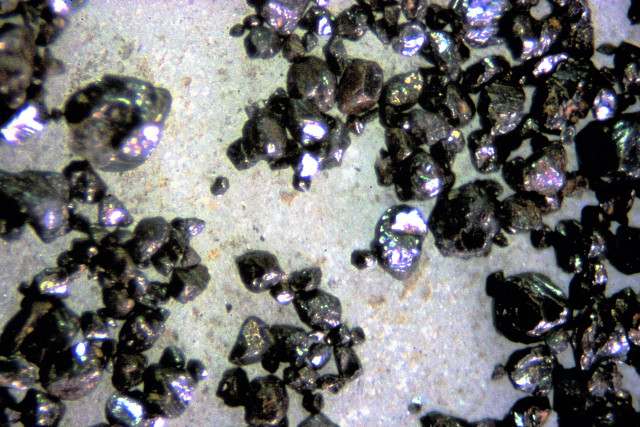
Figures 2 and 3: Examples of black magnetite sand in the wild
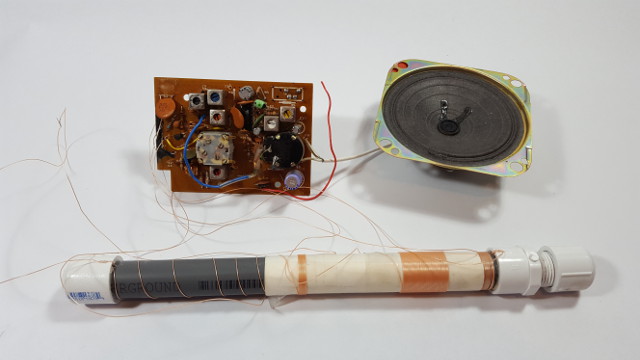
Figure 4: A modified AM radio using a black sand antenna
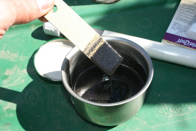
Figure 5: Black sand and resin slurry
Figures 6 and 7: Examples of cast bars
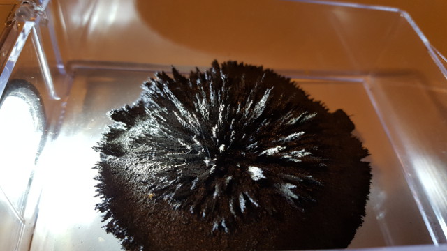
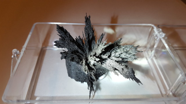
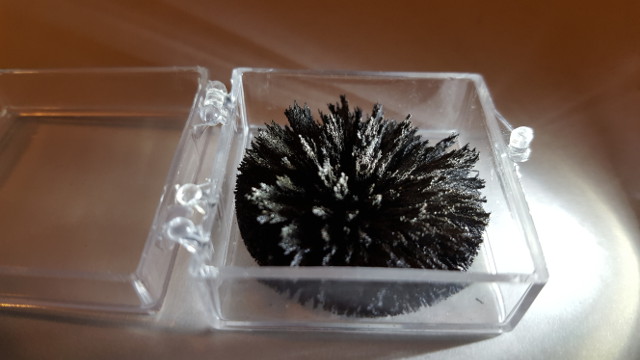
Figures 8 through 12: Flux lines "frozen" in resin
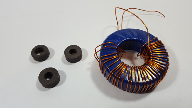
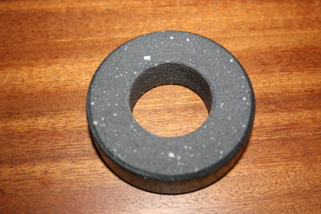
Figures 13 and14: Magnetic toroids fabricated from "black sand"
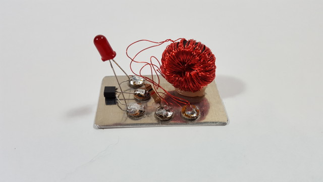
Figures 15: A "black sand" Joule thief
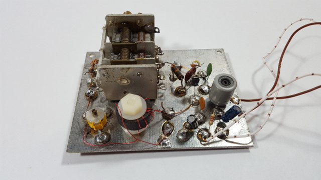
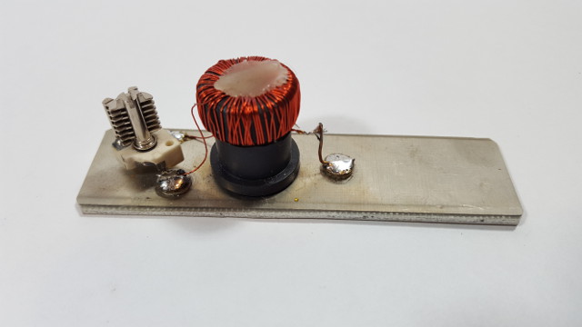
Figures 16 and 17: Left, a "black sand" RF oscillator, right, an LC tuned circuit
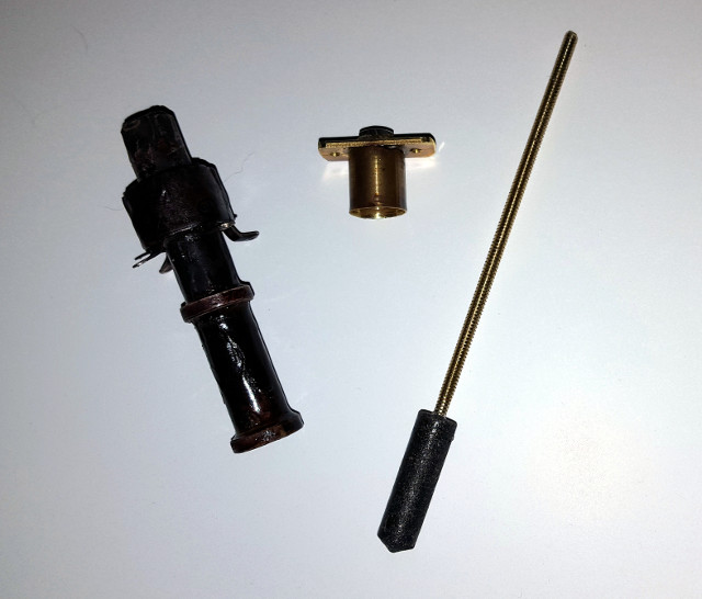
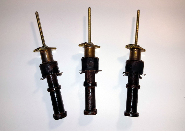
Figures 18,19, and 20: Home-made loop sticks
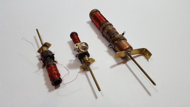
Figures 21 and 22: An experimental variable inductor
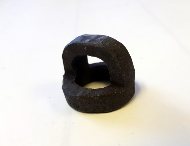
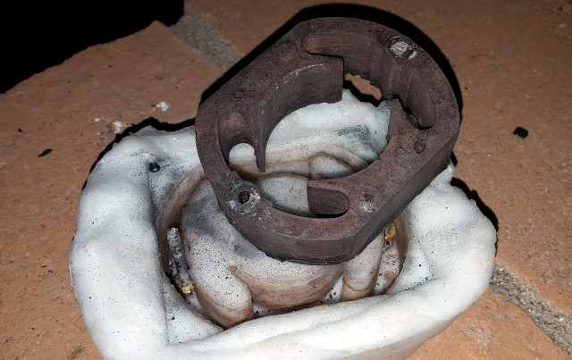
Figures 23 and 24: A home-made pot core transformer
Figures 25: Cast transformers
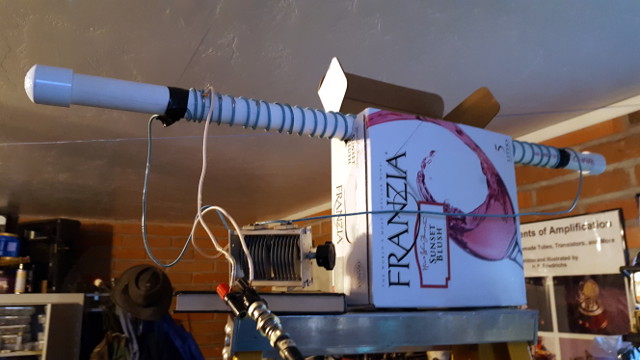
Figures 26: An experimental "black sand" transmitting antenna
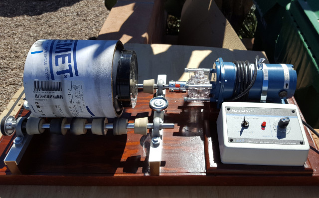
Figures 27: A homebrew ball mill
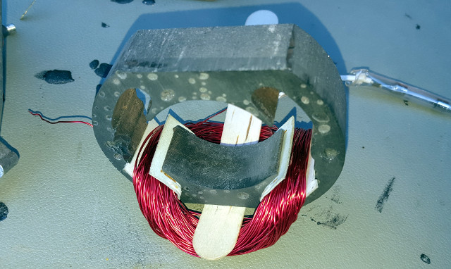
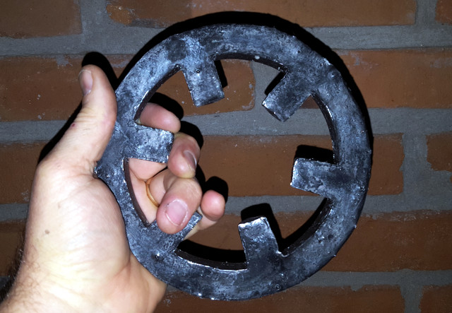
Figures 28 and 29: A cast universal motor field
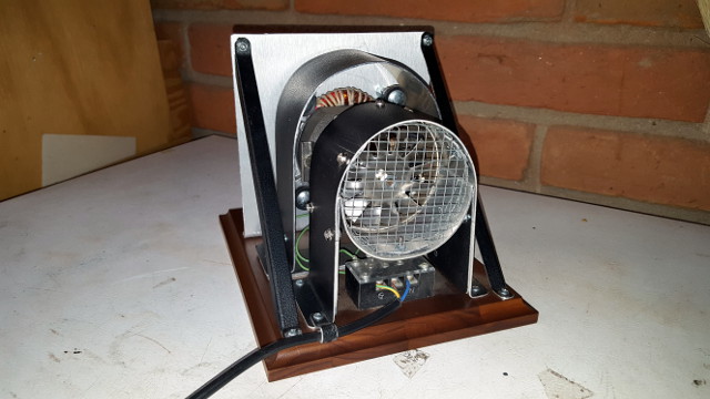
Figure30: A test fixture for the modified motor
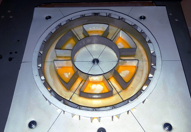
Figures 31 and 32: Left, the alternator stator mold, right, the cast stator
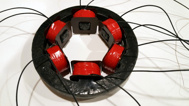
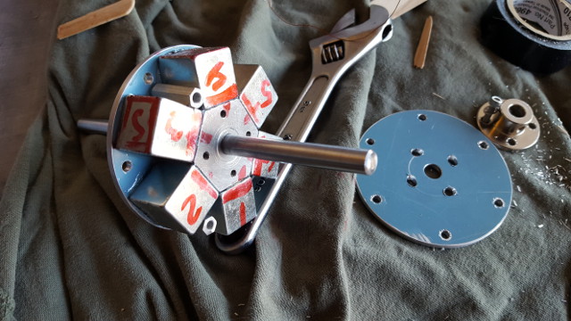
Figures 33 and 34: Left, a wound stator, right, the alternator rotor
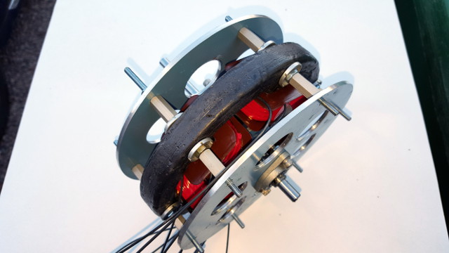
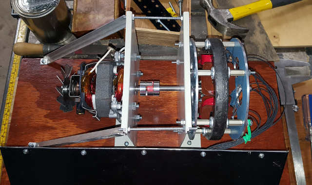
Figures 35 and 36: A half-kilowatt alternator and test stand
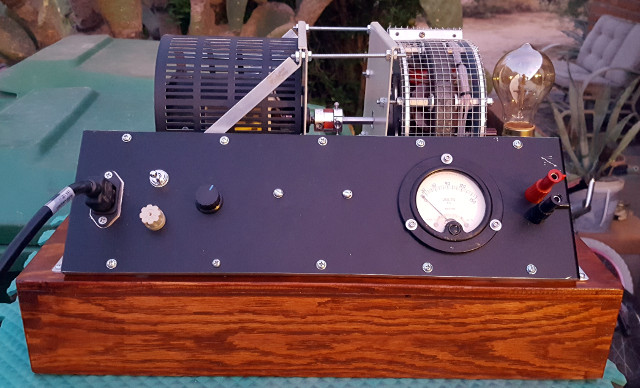
Figure 37: A half-kilowatt powered-iron alternator and test stand
Document Pilot, 09/04/2020