H. P. Friedrichs (AC7ZL) Homepage


Radio Room
Restoring the BC-348-Q
Introduction
The B-17 and its companions had penetrated deeply into enemy airspace. To this point, their journey had been quiet. Yet, once the massive formation had been detected, it was clear that the Germans had no intention of allowing them to proceed any further. All at once, the sky became peppered with large black puffs of smoke. Flack clattered like hail and tore through the fuselage. Daylight streamed in where it should not. Suddenly, there was a massive explosion. The craft shuddered, and a tattered engine burst into flames. The pilot cut the fuel to that engine and feathered its prop.
A large hole had appeared near the radioman's position, where he sat behind the bomb bay. Momentarily stunned, he gazed through the jagged opening and watched as an adjacent B-17 broke apart, rolled gracefully, and plummeted towards the Earth. Quickly regaining his focus, the radioman returned his attention to his mission and the communications equipment at his station... including the glowing dial of a BC-348.
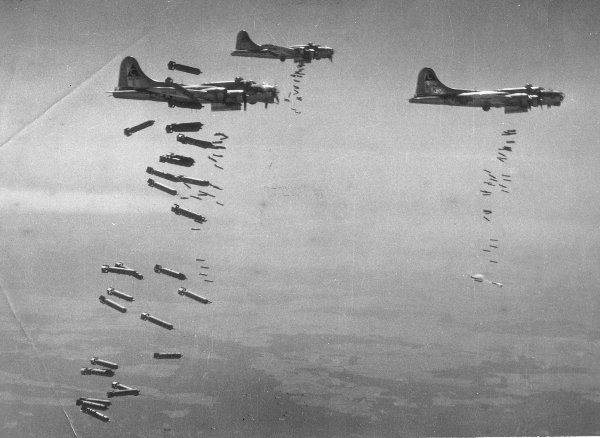
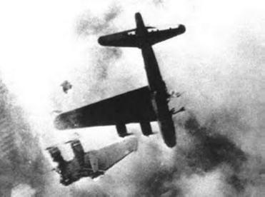
(Photos courtesy Sam Halpert and www.b17sam.com)
I blinked. In a heartbeat, my thoughts were transported from an imagined battle in the skies of World War II Germany back to the present. I stood at the tailgate of a friend's jeep on the grounds of the Cochise Amateur Radio Association's 2006 hamfest located near Sierra Vista, Arizona. He had brought some gear to sell at the 'fest, including a BC-348.
"Beautiful radio," I said, eyeing it jealously, "and a real piece of history. You're not selling that, are you?"
"I have more projects than time, " he confided. "I need to clear out a few things. I paid a hundred bucks for it, thinking I'd go through it and get it working, but I'd let it go for forty if you took it right now."
"Holy cow," I thought. I had more projects on my bench than time as well, but I couldn't pass this up. I withdrew two twenty-dollar bills from my pocket, and then carried the radio gently back to my truck. The old girl was secured in the passenger seat with the lap belt.
Some Background on the BC-348
On bringing my new treasure home, my first priority was research. Remember: Google is your friend!
From what I've gathered, the BC-348 is a design that dates as far back as the mid 1930's. By the late 50's when production ceased, some 100,000 sets had been produced. Its principle deployment was in aircraft, multi-engine transports and heavy bombers like the famous B-17, B-24 and the B-29. Photos of the radio operator's position in the Enola Gay seem to show a BC-348, so any radio traffic leading up to or following the detonation of the first atom bomb was probably carried, at least in part, on this kind of radio.
The "BC-348" nomenclature does not represent a specific radio, but rather, a family of radio sets. The members of the BC-348 series are denoted by a suffix letter. In the case of my radio, this is the letter "Q." There must have been a couple dozen variations of the BC-348, not to mention the BC-348's parent, the BC-224.
Most "boat anchor" enthusiasts (people fond of heavy, vintage, vacuum-tube-filled electronics) are well aware of the Boat Anchor Manuals Archive (BAMA) web site, an indispensable source of documentation on hundreds of pieces of older communications gear and electronic test equipment. The one drawback to BAMA materials is that, while accessing the archive is free, electronic storage still costs money. To optimize the use of their limited space, documentation files are sometimes scanned at a resolution that results in smaller files, but poorer images.
In searching the web, I was fortunate to stumble across James A. Moorer's BC-348 Receiver Page. Apparently dissatisfied with the quality of BC-348 documentation available on the web, Mr. Moorer took it upon himself to secure original copies of schematics, parts lists, and service information. He then scanned these documents at high resolution, generating PDF files of unprecedented quality. Like the BAMA materials, these superb documents can be downloaded for free. Many thanks to Mr. Moorer.
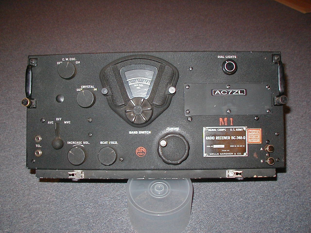
The BC-348 is a rugged, 8-tube, single conversion, superheterodyne receiver. It covers 200 kHz to 18 MHz, segmented into 6 bands. The AM broadcast band is omitted, probably because of the 915 kHz IF frequency. The radio features a BFO for copying CW (Morse), a crystal filter to reduce adjacent signal interference, and a switchable Auto/Manual AVC. The BFO frequency is adjustable, so the set can be used to listen to single-sideband.
Band switching involves an interesting combination of mechanics and electronics. The tuner dial is covered with a slotted shutter disk. As the different bands are selected, using the star-shaped knob on the front panel, the shutter disk rotates to expose only that portion of the tuner dial containing the appropriate frequency scale.
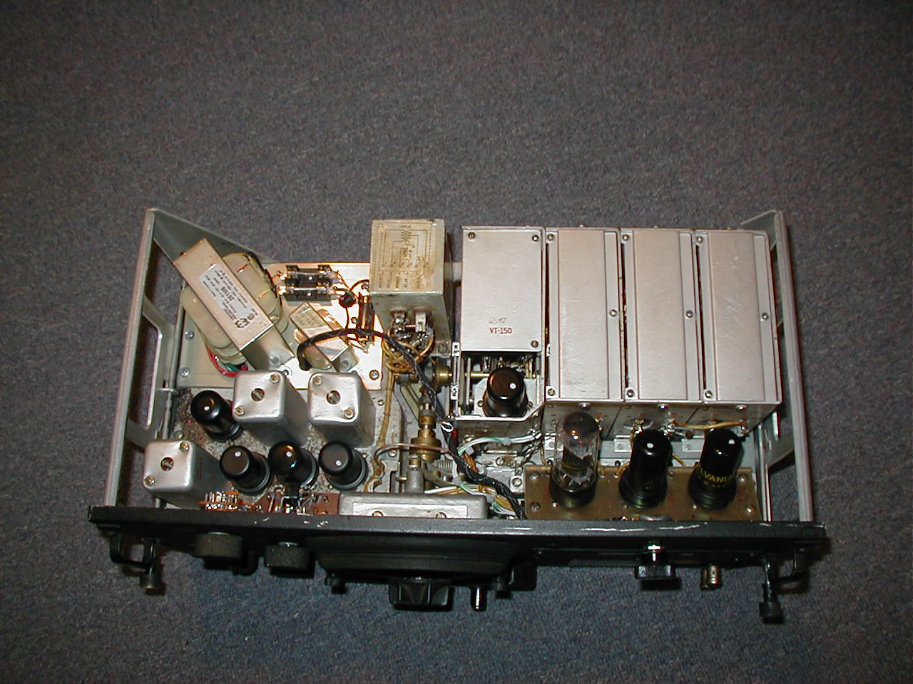
The four aluminum boxes at the upper right of the photo (above) contain circuitry associated with antenna tuning, RF amplification, first detection, and the local oscillator (ordered from right to left). Each box contains a wafer switch, and the switch in each box is coupled to adjacent boxes with a link-and-lever mechanism. In theory, this allows the boxes to be removed/replaced individually (though not without difficulty!)
Tuning, is performed with a four-section variable capacitor mounted on the underside of the chassis. The crank on the front panel drives the variable capacitor through gear-train composed of a brass worm and zero-backlash (spring-loaded) gears. For any given band, it takes about 100 turns of the crank to get from one end of the scale to the other.
Speaking of mechanics, this radio is no sissy. The frame is a substantial aluminum casting, covered with solid bracketry. The front panel is hefty, and the housing is a sturdy, welded, aluminum box. When issued, this radio weighed in at about 40 pounds!
Following World War II, lots of military equipment, including radios like the BC-348, appeared on the surplus market. This was to the utter delight of hams and radio tinkerers who purchased this equipment, dismantled it, and modified it. In fact, these days, finding a radio that is complete and unmodified is next to impossible.
Originally, the set was designed to be powered by the aircraft's 28-volt DC supply. The radio's tubes, whose filaments are 6.3-volts each, were wired in a series-parallel arrangement in conjunction with some ballast resistors. The 220-volts DC required for the receiver's plate circuit was provided by a dynamotor. (The dynamotor is a combination motor/generator...low voltage DC goes in, and high voltage DC comes out.) A common modification involved removing the dynamotor, rewiring the filament circuitry so that the tubes could be lit with a 6.3-volt transformer, and installing a power transformer, rectifier tube, filter capacitor, and choke to provide plate voltages.
Filament Problems
When I got my radio home, I opened it, not knowing quite what to expect. The chassis can be removed from the housing by loosening a pair of brass thumbscrews. The screws are located on the front panel, one beneath each of the two handles. Once these are loose, the chassis pulls out of the front of the housing.
It was no surprise to find the dynamotor missing, but there was no AC power supply either. However, someone in the distant past had been kind enough attach paper tags to four wires that apparently fed power to the set. One pair was labeled "A 6-volt" (obviously the filament supply) and the other "B Supply" (the plate supply). I scrounged together my bench supplies and some alligator-clip test leads. I plugged a set of high-impedance headphones into one of the jacks on the front of the radio set and powered up the supplies. I heard.....nothing.
All of the tubes in the set but one have metal jackets, so it's not really possible to look for the telltale glow of the filament in each tube. However, I felt them with my fingers and discovered two tubes that clearly were not getting warm. I powered down the set and began removing each tube, one at a time, for testing in one of my tube testers.
A 6SR7 (VT-223), used in this set as a 2nd detector, CW oscillator, and AVC rectifier was found to have an open filament. OK, that would explain a lot. What puzzled me was the other tube that failed to light. The latter, a 6SK7 (VT-117) forms the 2nd IF amplifier. Its filament tested good. What the heck was going on? Knowing I had a least one dead tube (and because some of the others tested weakly) I ordered a complete set of NOS (new-old stock) tubes from www.radiodaze.com. While I waited for the new tubes to arrive, I pulled out my ohmmeter and began tracing the filament circuitry.
I quickly found a wiring error made by whomever had attempted to convert the set's filament circuit from 28 to 6-volts. I contemplated fixing the error, but I was sufficiently displeased with overall modifications made by this person that I pulled out all of the cruddy wire he had installed, and rewired the filaments from scratch. I verified my wiring with my DMM, and installed a fresh set of tubes. I powered up the filaments and let the tubes get hot. Then I applied the plate supply. Nothing happened, at first. After several minutes, however, I could hear some faint audio.
Capacitors Gone Stale?
I began to suspect that the some of the set's 60-year-old capacitors had become leaky. I corresponded with some antique radio enthusiasts on the Internet, people who rebuild and restore electronic antiques on a regular basis. They agreed that replacement of the set's capacitors was not only indicated, but in the opinion of most, standard procedure above all else.
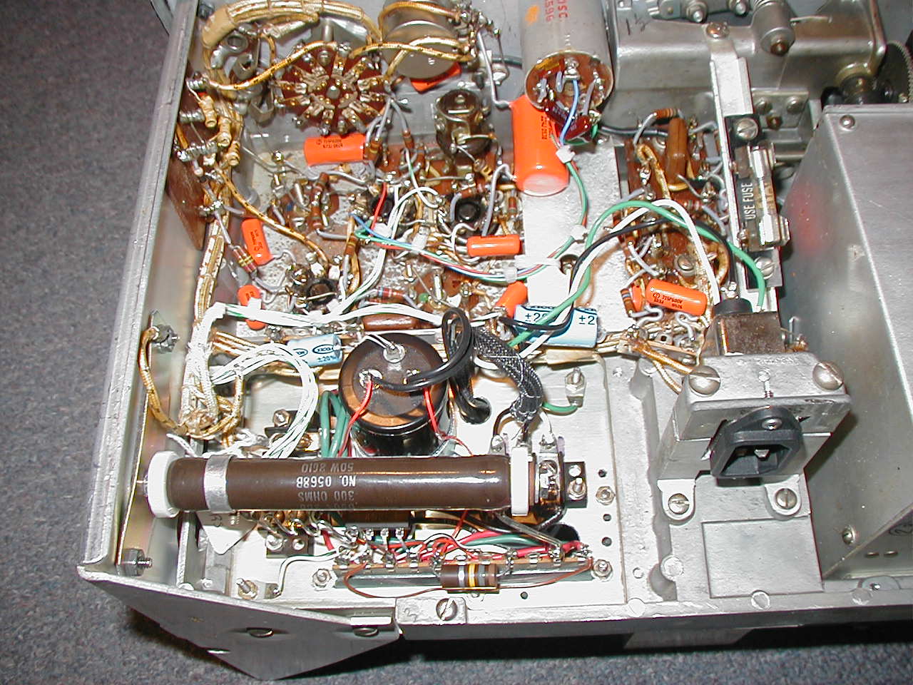
All electronic parts deteriorate with age, but among the worst offenders are electrolytic capacitors (used for power supply filtering and cathode bypass) and paper capacitors (used all over the place.) I conducted an inventory of the values I thought I'd need and placed an order with Mouser. All of the nonpolarized paper capacitors were to be replaced with Sprague "Orange Drops."
Using Moorer's documentation for reference, I removed and replaced offending capacitors one at a time. The leads of the replacement capacitors were fitted with Teflon "spaghetti" tubing, both to preclude accidental short circuits and improve the appearance of the repair work.
Bad Resistors, Too?
In performing the capacitor changes, I stumbled across a fractured carbon resistor associated with the 1st RF amplifier. The resistor was not burned or otherwise damaged, but it had simply cracked in half. This made me very suspicious of the resistors elsewhere in the radio. I began probing with an ohmmeter, but because of circuitry constraints, it was not always possible to measure the true value of a given resistor without unsoldering one of its leads. After I'd gone to this trouble a number of times, and discovered resistors whose values had drifted excessively, I decided to bite the bullet and replace all of the resistors in the radio. Like the capacitors, they were replaced, one at a time, and fitted with Teflon "spaghetti." The replacement resistors looked so much like the originals that the tubing actually helped me keep track of what I had and had not replaced as the work progressed.
Eventually, I worked my way from one end of the radio to the other and completed the job. This time, when I applied filament and plate power, Bingo! I was able to hear some kind of signal on every band!
What Happened to the BFO?
While the receiver seemed to work, I quickly discovered that it still had problems. First, the crystal filter was completely nonfunctional. When activated, the audio went dead. Second, the BFO didn't seem to work. I tuned to the low end of the 40 meter ham band, expecting to find Morse traffic. Yes, I could hear very faint puffing sounds consistent with Morse characters, but not the musical tones that should be heard when the BFO is on.
I tested the BFO and the crystal filter switches using an ohmmeter. Both switches were intermittent, but not as one might expect. I exercised the knobs while I watched the meter and discovered that both switches were sometimes on when they should be off, and other times they were off when they should be on. I unsoldered and removed both switches and bypassed them, as necessary, with alligator leads. Both the BFO and crystal filter remained nonfunctional.
I corresponded with another ham on the Internet, and he suggested that the crystal filter in the BC-348 may go "dead" with age and contamination. He proposed that it might be restored with a thorough cleaning. Using a blow dryer, I melted the beeswax sealing the crystal case, and soaked up the wax with a piece of cotton cloth. I removed the two screws in the crystal housing, dismantled it, and then scrubbed and soaked the various parts in alcohol. When I was satisfied that everything was clean, I air-dried the parts and reassembled the crystal. Prior to engaging in this operation, I had connected the crystal to a signal generator and a scope in the hope of identifying the crystal's resonant frequency. The crystal initially behaved like an open circuit. Once it was cleaned and reassembled, however, the scope showed strong resonant activity at around 914 kHz. I replaced the filter switch with a new unit from Mouser and reinstalled the crystal. The filter circuit was now functional.
Fixing the BFO was largely a process of elimination. I had already repopulated the receiver with new resistors, capacitors and tubes. The bad BFO switch was bypassed. The only piece of BFO circuitry not accounted for was the BFO coil, and the three mica capacitors soldered to the coil itself. I removed the coil and tested it for continuity. It checked out fine. There was nowhere to go with this line of troubleshooting but to replace the mica caps. I installed fresh caps and reinstalled the coil along with a brand-new BFO switch. I was pleased to find the BFO working splendidly.
Where's a Cat When You Need One?
At some point in this receiver's life, it had become temporary lodgings for a mouse. To a mouse, there is no part of any vintage radio that doesn't look like a urinal, nor will a mouse draw any distinction between the insulation on a wire and a block of cheese -- either one represents lunch. I did what I could to clean up the evidence of his visit by using alcohol and a cotton swab. Since I had already rewired significant portions of the set, I replaced any wire that appeared to have been chewed on. In addition, I discovered segments of wire that went no place-- remnants of modifications made to the set in prior years. These superfluous conductors were removed.
A Permanent Power Supply
Once the major functional problems of the set had been fixed, I turned my attention to the issue of power. There are two schools of thought with regard to homebrew BC-348 power supplies. The first camp says that a power supply can be constructed and installed inside the radio where the dynamotor once resided. The opposing opinion says that power supplies should be located external to the radio, to avoid radiating additional heat into the interior of the set. The latter opinion, I reasoned, was probably formulated in an era when plate supplies still employed sizzling-hot rectifier tubes. I concluded that if my supply was rectified with silicon diodes, it could probably be installed inside the radio without adding significant amounts of heat.
The original dynamotor bracket mounted into a rectangular opening in the radio chassis, and was secured by four screws. I fashioned an aluminum plate of comparable size, complete with mounting holes, and used this as the base for my supply.
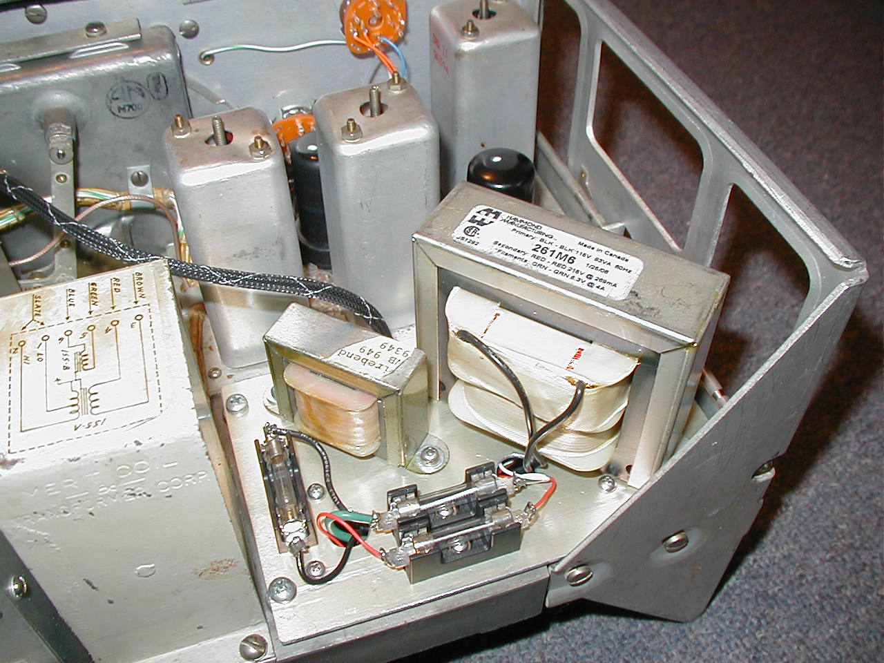
I purchased a Hammond power transformer from www.radiodaze.com, part number HX261M6. This transformer is capable of supplying 6.3-volts at 4-amps, and 215-volts at 270 ma. My supply was wired according to the schematic posted here. The tube filaments are fed raw AC., no problem. The plate supply is composed of a 1000-volt 4-amp rectifier bridge feeding a 300-ohm, 50-watt ballast resistor, followed by a pi-filter composed of two 50-uF electrolytics tied together with a filter choke. The choke was a junk box special, and measured about 2 Henries. A bleeder resistor will drain the filter capacitors if the supply should become disconnected from the radio. This configuration generates about 250-volts D.C., a value somewhat higher than the 220-volts that the original dynamotor would have supplied. However, I do not believe that this is problem for two reasons. First, the 220-volt dynamotor value is a nominal figure; the dynamotor output was probably subject to considerable variation. Second, all of the new capacitors installed in the set are rated at more than twice the 250-volt value, and few will ever see full plate voltage anyway.
Note that the primary, plate, and filament circuits are individually fused. The plate and filament fuses are intended to protect the radio. The primary fuse is for safety, and intended to protect me and my house.
Power was originally delivered to the BC-348 through a special plug at the rear of the set, comprised of 8 rectangular blades. The connector on my radio had itself been modified, and some of the wiring that left the plug went no place. In the end, I decided to remove it entirely. The upshot of this decision was that the plug's support bracket provided the ideal place to mount a standard IEC power plug (the kind found at the rear of your computer.) I selected a plug that features an integral noise filter to shield the radio from any hash (EMI) that might be present on the power mains.
One final problem lingered. The radio had once featured a knob used to dim the tuning dial lamps. Somewhere along the line, somebody must have dropped the radio and broken off the knob. I could still turn the stub of the broken shaft with a pair of pliers, but the dial lamps refused to light. On closer examination, I found more wiring problems. In the end, I decided to eliminate the dimmer rheostat completely, and wire the dial lamps directly to the filament supply. I like the look of the full-brilliance display anyway.
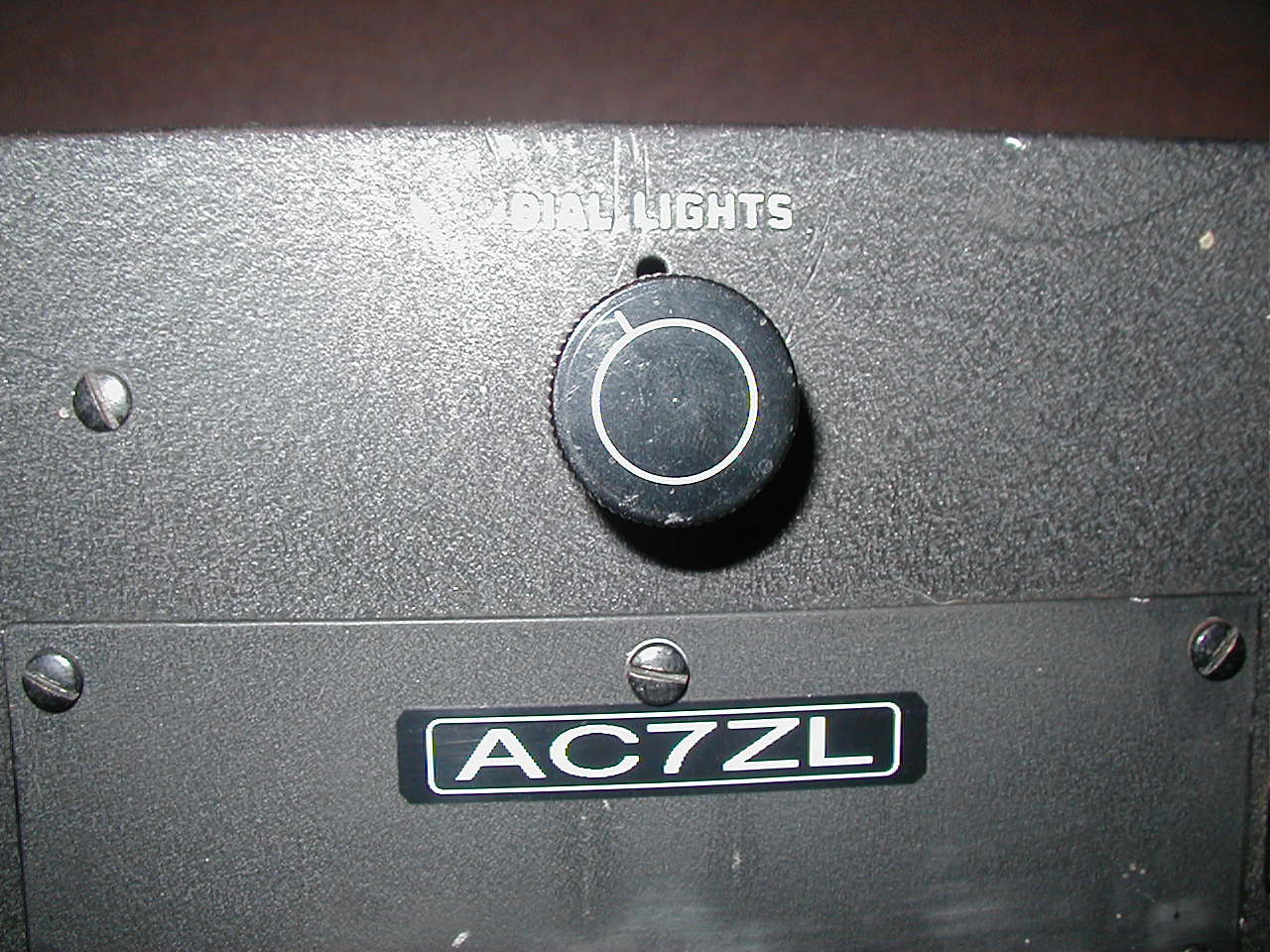
I needed to add an on/off switch for my new power supply, but I didn't want to alter the front panel by drilling any new holes in it. The hole vacated by the rheostat was the ideal place to add the new power switch. I chose a rotary-type switch and fitted it with a metal knob from my junk box. It's not a perfect match, but it's fine until I can find something better. Perhaps a shot of flat black paint will help the knob blend with the others a little better.
Alignment, Operation, and Performance
Alignment of the set is not overly difficult, and once again, Moorer's excellent documentation gets the credit. The BFO and AVC are turned off, a signal is injected into various places in the IF chain, and the IF cans are tuned up, one at a time. When this is complete, a signal is injected into the antenna terminal, and trimmer caps are tweaked to peak the receiver's response and ensure proper tracking on all bands.
I noticed that the crystal filter, while functional, exhibits a lot of insertion loss. To minimize this, I measured the crystal's resonant frequency again (914.180 kHz) and then realigned the IF transformers to this frequency as opposed to the nominal 915 kHz. The crystal filter seems to work much better, now.
Overall, the performance of the set is good, though there are a few areas of disappointment. The first issue is tracking. Despite my best efforts, I never could get the set to track properly on any band but the first. I have scratched my head over this for quite a while now, and I am slowly coming to the conclusion that this may have to do with the drift of capacitor values inside of the aluminum band switch boxes. All of the bands have peaking trimmers, but only the lowest band has a "padder." The only real solution to this problem, as far as I can tell, is to remove and dismantle each of the aluminum band switch boxes and replace the caps inside. This is more hassle than I am willing to go through right now, so this may have to wait for a rainy day in my retirement.
My second complaint has to do with selectivity. It's not bad, subjectively speaking, but I can't envision using this receiver much for CW... there is simply not enough signal separation. Somebody suggested to me that the capacitors inside of the IF transformer cans may have become leaky, degrading the Q. They claimed this was the case with their radio, and that with the caps replaced, selectivity became much better. Perhaps so, but like the tracking issue, this is a project for another day.
Finally, while the tuning on this set is exceptionally precise, the bands are so wide that the resolution of the tuning markings is comparatively poor. Yes, the radio works fine for casual listening on ham and shortwave bands, but you will never know better than your approximate frequency.
All said, it's worth keeping this radio's performance in perspective. As a fellow ham and friend of mine observed, "...these radios were not to designed to work great. They were designed to work good enough....while you are being shot at." This radio certainly works "good enough," and whatever its technical shortcomings, the set more than makes up for them with character, aesthetics, and historical appeal.
The Ethics of Radio Restoration
The repair of any kind of vintage electronics will always pose a moral dilemma of sorts. What is the ultimate goal? Authenticity and functionality are sometimes mutually exclusive objectives.
I know of antique radio enthusiasts who would prefer a radio complete and "mint" with as-issued components even if it no longer plays. Others are willing to make repairs, but only if these repairs are invisible. They will carefully dismantle old cardboard capacitors, for example, hollow out the expired guts, and then "stuff" the emptied housings with new parts.
At the other end of the spectrum are those who, while perhaps technically competent, have little sense of history or of an obligation to protect the artifacts that express our history. They will happily cut, drill, saw, and solder until the equipment in question does they want it to do. Some will go so far as to take vintage collectables and "chop" them, so that they can sell the parts at a premium on Ebay. To each his own, but I can't help but feel a certain twinge of sadness when an auction's descriptive text reads, "...removed from working equipment."
I have no doubt that one of the restoration purists mentioned earlier would be horrified by the repair work I've done to my BC-348. Teflon wire? A silicon rectifier bridge? Sprague Orange Drops with 2006 date codes in a 1943 radio? Sacrilege!
Not quite. While my own sympathies tend to lie with the purists, I also think that repair/restoration decisions need to be made on a case-by-case basis. For example, when I was 9 or 10 years old, I purchased an early 1900's crystal radio set at a garage sale for seventy-five cents. Though literally hundreds of old televisions, radios, and toys gave their lives so that I might become a proficient electrical engineer, I never once considered doing anything to that old crystal set but dusting it and oiling the wood from time to time. Now displayed under a bell jar, it remains with me, as I found it, to this very day.
In the case of my BC-348, the missing dynamotor, the bad switches, the broken dimmer, and the poorly executed modifications by both mouse and man, (not to mention the fact that somebody had attempted to ventilate the cabinet by drilling a pattern of small holes in the back,) all conspired to assure that this set would never be "mint." In a certain sense, this realization was liberating, as it eased my conscience about taking those steps necessary to return the radio to service. No, I do not feel bad about the Orange Drops, the line filter, or my safety fuses. These were a small price to pay for returning the voice to an instrument that had probably sat mute for more than a half-century.
What is important is that both the appearance and spirit of the radio remain fully intact. I purposefully avoided drilling any new holes in the front panel or cabinetry. I did not add new features or make modifications that materially altered the behavior of the set. In fact, everything I've done can be un-done, should some future owner be inclined to do so.
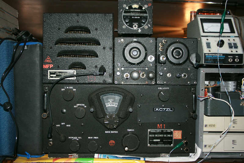
Web Article Update: Some Nice Radio Upgrades
Since the above text was prepared, I've had the opportunity to put some finishing touches on my BC-348. These can be seen in the photo above.
The first upgrade involves the light dimmer knob. As you've just read, the original knob was missing, and I had replaced it with a similar, but non-authentic knob. Surfing through Ebay pages one day, I found the correct knob for sale. I snatched it up for a few bucks and installed it the moment that it arrived.
The other upgrade involves a matching speaker cabinet. To this point, I had used the radio, either with headphones, or with a Rube Goldberg arrangement consisting of a phone plug, alligator leads, a matching transformer, and a loose permanent magnet speaker.
While surfing the 'net, I discovered an offer by Fair Radio Sales for a model LS-3 speaker. The LS-3 is composed of a heavy, felt-lined, steel, military-style cabinet, a permanent magnet driver, and an internal matching transformer. Strickly speaking, I'm not certain the LS-3 is historically correct for use with the BC-348, but it was used with similar radios, and looks fine along side my set.
I discovered that, while the phone jack appears to be of the normal 1/4-inch variety, it is in fact somewhat smaller. I removed this jack and replaced it with its quarter-inch equivalent. A short, black patchcord, purchased at a nearby music store, is used to connect the speaker to the radio.
Useful and Interesting Links
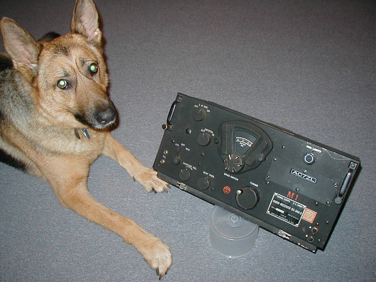
Charlie, who supervises all of my projects, is also a fan of the BC-348-- he insisted on posing with the radio. He recommends the following links to anyone interested in additional background information on this radio and its application.
| BC-348 Technical |
|
|
James Moorer's BC-348 Page |
|
|
Boat Anchors Manuals Archive |
|
|
BC-224 and BC-348 Aircraft Radio Receivers |
|
| Sherry's Boat Anchors |
|
| The Military Radio and Wireless Workshop |
|
|
The Irrepressible BC348 Receiver |
|
|
|
|
| Aircraft History |
|
|
BC-17 Sam |
|
|
B-17 Bomber Crew Interview |
|
|
Arizona Wing CAF |
|
| B-29 Photo Museum |
|
|
USAAF B-17 B-24 B-25 B-26 B-29 |
|
| Aluminum Overcast |
|
|
Diary Of A B-17 Ball Turret Gunner |
|
| John Ellsworth Asmussen B-17 |
Document Revision 1, xx/xx/xxxx
Document Revision 2, xx/xx/xxxx
Document Revision 3, 07/04/2007
Document Revision 4, 05/19/2009