H. P. Friedrichs (AC7ZL) Homepage


My Projects
Audio Equipment:
A Flat Response Mike and Channel Amplifier
Summary
A painting hung on a wall with garish wall paper will likely appear different than the same painting hung on a plain white wall. That same painting may look different again, depending upon whether it is illuminated by sunlight through a window, an incandescent bulb, or a fluorescent lamp.
In much the same way, the physical attributes of room, its dimensions, the wall materials and coverings, floor materials, ceiling treatment, windows, and furniture placement all conspire to "color" sounds in that room.
Most people care little about these effects. On the other hand, those effects can be critical in settings like churches, theaters, or the living room of a discriminating music lover. A room's tendency to resonate at certain frequencies and cancel others can lead to a "muddy" sound, a loss of acoustic clarity, or difficulty in understanding program material despite adequate volume.
One way to quantify the acoustic properties of a room is to generate tones of varying amplitudes and frequencies, play them through speakers, and then sample the sounds produced with a microphone. The signal can then be fed to a spectrograph, an instrument that shows variations in a signal's phase and spectral components.
Once a room's acoustic behavior has been measured, one can take steps to rectify any shortcomings that are uncovered. This may including moving or adding speakers, changing EQ settings, introducing audio delays, adding/removing curtains, adding/removing wall treatments, or moving furniture.
Interested in making these kinds of measurements, a colleague of mine purchased a piece of commercial software called ETF 5, distributed by Acoustisoft. Installed on a laptop computer, this software generates tones and is able to perform detailed analysis of audio signals collected by a microphone. This of course presumes that one has a suitable microphone and preamp, which is where I came into the picture. He asked me if I could build a microphone and preamplifier circuit for use with his software.
Since the point of this exercise it to measure the extent to which a room's attributes color sound, it follows that the microphone used to sample sound should not add any coloration itself. In other words, it should have as flat and uniform a response as possible. Additionally, the microphone should be capable of reproducing a wide range of sound pressure levels, from a soft whisper to crashing thunder. Furthermore, I inferred from my friend's interests that portability or semi-portability would be an attractive feature. This implies rugged construction and the option of battery operation. What follows is the description of a microphone and preamp system that I designed for use with ETF 5 or similar software.
My Microphones
Below is a photo of one of two microphones I fabricated for this project. The body consists of standard copper caps, couplers, and tubing. The various pieces were sweat soldered together, with the exception of the end cap, to the right, which is held in place with a 4-40 screw. The end cap houses a 3.5 mm stereo phone jack, used to power the microphone and conduct audio signals.
The "stem" of the microphone is fashioned from brass tubing, and is attached to the microphone body with a brass compression coupler. This allows the stem to be removed for servicing, if necessary. Both the stem and microphone body are packed with cotton and sponge foam to dampen ringing. For the same reason, the stem and body are covered with sleeves of made from heat shrink tubing.
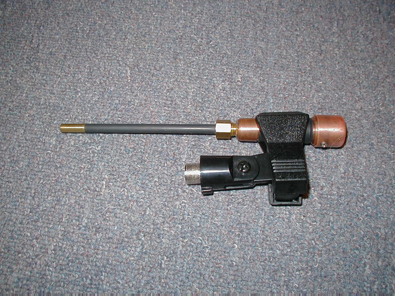
The microphone capsule, installed in the end of the stem at the far left, is based on the Panasonic WM61A condenser capsule. The capsule, however, is modified. Normally, these capsules are two-terminal affairs. One terminal is fed power through a resistor, the other terminal is grounded. The audio signal appears at the junction between the supply resistor and the capsule. Inside of the capsule is a FET which varies the current drawn through the supply resistor in response to sound waves. This topology works fine, but limits the dynamic range of the capsule.
By performing "surgery" on the capsule, it becomes possible to insert a resistor at the ground end of the FET, instead of the supply end. This revised topology is more like a source-follower. It allows the capsule to be used at higher sound pressure levels because the reduced gain of the source follower topology prevents clipping. The mike's internal schematic can be found here.
The microphone requires a clean, regulated power source, and suitable amplification to boost the signal to a level suitable for use by the laptop software.
My Preamps
My preamps provide two selectable gain ranges, and an attenuator or trimmer for fine level adjustments. The preamp is based on the TL084 FET op amp, and features three stages of amplification. The schematic can be found here.
Below is a photo of the circuit board in one of the preamps. Being a prototype design, I used point-to-point wiring. Gain resistors were mounted in headers and plugged into DIP sockets. I did this so that it would be relatively simple to make changes to the preamp's gain, should that prove necessary.
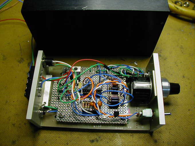
The adjustable attenuator on my preamps is implemented with a 10-turn precision pot. The pot is fitted with a mechanical turns counter, and a brake lever that will lock the attenuator in any present position.
The housings for my preamps are recycled materials, salvaged from discarded electronic equipment. The cases are anodized aluminum, with thick aluminum front and back plates. In other words, these are very rugged.
The Complete Kit
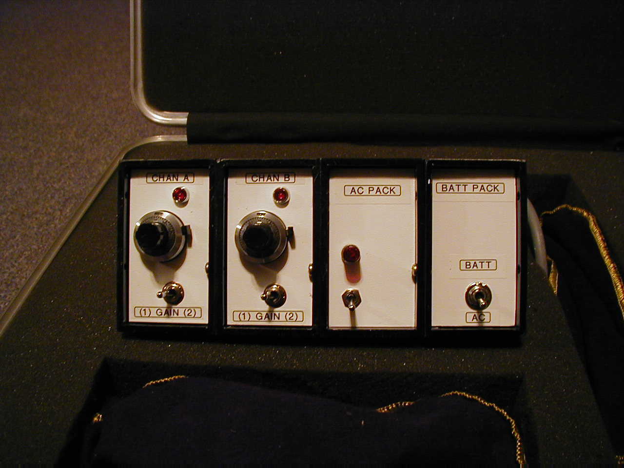
I built a pair of microphones, thinking that it would be nice to make measurements in stereo. This required two preamps. The preamps need a split power supply, which I provide through two means. The first is a regulated +/- 15 volt, AC powered supply. The second power source is a pair of 9 volt batteries for operation where an AC outlet might not be readily reachable. The preamp and supply modules are bolted together to form a rugged block of instrumentation.
Standard 3.5 mm shielded stereo cables are used to link each microphone to its respective preamp, and a dual-phone-jack-to-3.5mm-stereo plug is used to connect the preamps to the laptop computer. A logical accessory to this set up is a pair of microphone clips to allow the attachment of the mikes to a suitable microphone stand.
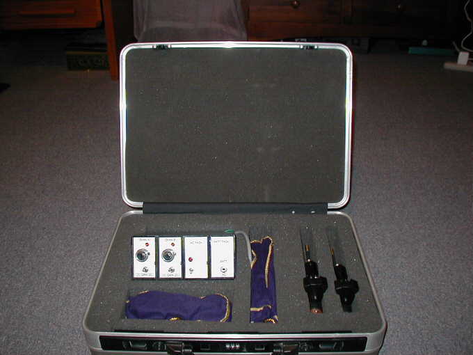
I decided that it made sense to house all of these pieces together. Luckily, I had purchased a very old camcorder at a church sale about 6 months earlier. I had dismantled the camcorder for parts, but kept the case. This case seemed an ideal candidate for use with this project.
I found a block of gray foam, and cut the necessary openings with an electric carving knife. The results can be seen below.
(Revised 08/04/06)
(Document Revision 2 12/28/2008)
(Document Revision 3 04/29/2009)