H. P. Friedrichs (AC7ZL) Homepage


Radio Room
Vacuum Fluorescent Display Amplifiers For Primitive Radio
Introduction
Vacuum tubes represent an electronic technology whose roots extend a century and more into the past. With the exception of their continued use in certain niche applications, they have all but vanished from contemporary electronics, having been replaced by an endless array of solid state switching, amplification, and display technologies. Yet, despite all of this, it seems that interest in vacuum tubes and the "hollow state" technology that makes them work refuses to die.
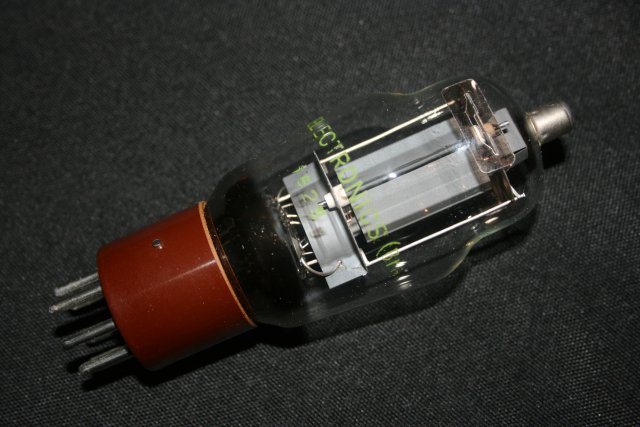
A Typical Vacuum Tube
I’ve done a fair bit of tinkering with vacuum tubes, even to the extent of building a few of my own. I actually wrote a book about it. This article, however, comes from a different vantage point. In essence, I’ve identified a piece of contemporary electronic junk that, while not intended to be a vacuum tube in the classic sense, shares the necessary features of radio tubes. It can be induced to amplify feeble audio signals from primitive radio gear like crystal radio sets. Such experimentation is a lot of fun, and the end result is actually useful.
That said, let us not overlook the fact that most vacuum tube experiments, including the ones to follow, involve the use of high voltages. Besides the obvious dangers associated with electric shock, miswired batteries can overheat and short circuits can produce fire. My presumption is that the reader is familiar with basic electrical principles, competent with regard to safe practices, and endowed with some level of common sense. Remember, you are responsible for your own safety.
Basic Tubes
Before I describe what I’ve been playing with, it is worthwhile to engage in a quick review of what makes a classic vacuum tube what it is. It would actually take volumes to discuss this in a comprehensive manner, but let’s summarize things this way. We start with a common light bulb, that is, a wire filament contained in a glass bulb from which all the air has been evacuated. If we add a metallic plate to the interior of the bulb, and place a positive charge on that plate, electrons will actually leave the surface of the heated filament, float through the space between the filament and plate, and strike the plate. In other words, an electric current can be made to flow between the filament and plate. Current will not flow from the plate back to the filament, making such an instrument a one-way check-valve, or diode.
The diode form of tube has numerous applications, not the least of which is the extraction of audio from amplitude modulated (A.M.) signals. But let’s put that aside for the moment.
Once we set things up in the tube described above, the current between the filament and plate is constant. However, if we introduce a wire mesh or "grid" between the filament and the plate, and then apply varying electrical charges to that grid, we find that the flow of current between the filament and plate will also vary. This is the essence of amplification—the idea that a tiny signal can be used to control the flow of a more powerful energy source.
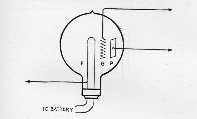
The triode (From Vacuum Tubes in Wireless Communication, Bucher, 1919)
.
The Vacuum Fluorescent Display
Many of the electronic gadgets in the modern world speak to us through information displays of some kind. All sorts of display technologies are used to communicate functional status and numeric values like time, voltage, temperature, weight, and mileage. Among these is the vacuum fluorescent display, or VFD.
VFDs are luminescent displays, that is, they glow. VFDs typically emit a pleasing blue-green light, and the glowing images produced by the VFD can be fashioned to represent numbers, letters, bar graphs, icons, or other symbols. Where can one find VFDs? Everywhere! They are commonly used as displays in appliances like microwave ovens. They are used in industrial electronics like digital panel meters and thermometers. I’ve seen them in toys, bathroom scales, stereo equipment, and office phones. The information display for the entertainment system in my 2008 Ford is a VFD.
Internal Structure of the VFD
Like a vacuum tube, a typical VFD consists of a glass container from which all the air has been removed. Because VFDs are display devices, the glass envelope tends to be somewhat flat and rectangular in shape. The display characters-- the symbols, words, and segments that actually light up-- are composed of electrodes called anodes that are coated with phosphorescent chemicals. Typically, these chemicals contain zinc, selenium, sulfur, and other trace materials.
Stretched across the interior of the container, suspended above the display characters, are several filament wires. These wires are powered by a low-voltage supply to heat them. Although these filaments lie between the observer and the characters, they are composed of exceedingly thin wire and are not heated to more than a very dull red, so you wouldn’t even notice them unless you actually looked for them.
If we apply a source of low voltage to the filament, it will heat up and generate a cloud of electrons. If we then apply a high-voltage positive charge to the character’s electrodes (the anodes), electrons produced by the filament will be attracted to this positive charge, and will strike the phosphorous chemical coating on the characters. When stimulated in this fashion, the characters glow.
Of course, when the display is in use, we don’t want all of the display items to be glowing at once. Rather, we want to be able to control the display features independently, and turn them on and off as necessary. To enable this, VFDs contain another structure: a thin mesh or grid that lies between the filament and each phosphorescent display feature. If we apply a positive charge to the grid, electrons from the filament are encouraged to move toward the phosphors and induce them to light. If a negative charge is applied to the grid, electrons from the filament are repelled, they fail to reach the phosphors, so the display feature goes dark.
Below is a photomicrograph of a section of a typical display. In this image one can see a display feature/anode (the word "TEST"), a honeycomb-like control grid that covers the word, and one of the display’s five filaments, which appears as a thin, white, horizontal line suspended above the grid.
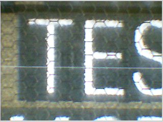
Internal features of the VFD
While the purpose of a VFD is very different than that of the average radio tube, there are similar structures in both. Both contain an electron source, the filament. Both contain a positively charged target. In the radio tube, this electrode is called a "plate." In the VFD, this electrode is called an "anode," and takes the form of a phosphor-coated word, symbol, or display segment Finally, each device contains a grid structure, which is used to control the flow of electrons from the filament to the anode/plate. The similarity between VFDs and the types of radio tubes I’ve been used to playing with prompted me to wonder if a VFD could be used as an amplifier. Interestingly, the answer is a definite yes.
Wiring Up a VFD
Wiring up a VFD is a simple matter. The key is knowing which terminals on the VFD do what. This information can be arrived at in two ways. If one is lucky, a Google search of the part number for a display may yield a manufacturer’s datasheet. A datasheet will indicate which pins are connected to which internal structures, and it will also provide useful information regarding the proper voltage to apply to the filament. The other way to derive hookup information is to study the display visually, make a few measurements with an ohmmeter, and deduce what one needs to know from these observations. My VFD’s were salvaged from junk, so I took the latter route.
The first step is to identify the filament terminals. The filaments appear as long, thin, hair-like wires that run parallel to the long axis of the display. I would expect to find at least three, or possibly more, but the exact number depends upon the type and dimensions of the display. The ends of each filament wire terminate at little metal bars or tabs. The tabs feed electricity to the filaments, support them, and in some cases, maintain tension on them so that they won’t sag. The first goal, then, is to study the VFD and its internal structures to determine which pins are connected to the filament.
The VFD’s internal structures are connected to external pins through strips of thin metal or conductive traces that are applied to the glass inside of the VFD. Knowing this, one can simply follow the path of these traces with the naked eye.
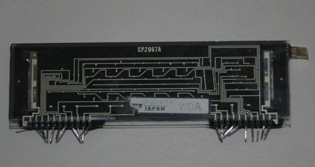
Traces on the backside of the VFD
Once a pair of filament terminals have been identified, they can be verified with a multimeter set to read ohms. If one probes between suspected terminal pins, one can expect to see conductivity and a resistance reading one the order of 10’s of ohms.
Next, one must identify the pins associated with each character or display feature, the VFD’s anodes. This is purely a matter of visual inspection. One chooses a display feature-- a word, symbol or perhaps a segment of a numeric figure-- and then tries to identify a signal path from that feature back to one of the external pins. This determination must be done for all of the display features. As my VFD was a reasonably complex device, I recorded which feature/anode connected to which pin on a sheet of lined paper.
Finally, all of the grid connections must be identified. This is also a visual exercise. One must choose a grid, study the VFD’s internal construction, and identify a path from that grid to one of the external pins. This must be repeated for each of the grids in the VFD. Again, I found it helpful to record my findings on paper as I studied the device.
Lighting Up the VFD
Lighting up the VFD requires two power supplies, a low-voltage supply for the filament, and a high-voltage anode supply to light up the characters.
Filament power requirements differ depending upon the specific VFD. However, of the parts I’ve tinkered with, the lowest filament voltage I saw was on the order of 3 volts, and the highest appeared to be 6 volts. I would suspect that other VFD’s have requirements that will fall in this range.
Filament voltages are easily achievable with flashlight batteries. Two "D" cells wired in series will get you 3 volts. For a 6-volt filament, 4 "D" cells in series are the answer. Batteries work just fine, but I preferred to take advantage of one of the variable power supplies on my bench. In any event, the supply is connected to the filament terminals that were identified earlier. When all is well, the filaments should barely glow when viewed in a darkened room. If the filaments are bright red, this is indicative of filament voltage that is far too high. Continued operation at this level will eventually burn out the display.
VFD’s also require a high-voltage supply to light the display features. In normal use, the "high-voltage" supply can actually be quite low, i.e., I have lit VFDs with as little as 15 volts on their anodes. However, in the radio application I am about to describe, higher voltages work much better. In that case, a D.C. power supply on the order of 90 volts or greater is just the ticket.
As is the case with filament voltages, the high-voltage anode current can be supplied with batteries. Ten 9-volt batteries, connected in series, will deliver 90 volts. Given the modest energy requirements of the VFD, batteries are a practical power source, and ten batteries in series should last a long, long time.
A comment is in order, here. A 90-volt battery is capable of inflicting an unpleasant shock. There is also sufficient energy in such a battery to cause a fire if it is abused. I have built high-voltage batteries of this type myself. I always prefer to install them in an insulated container, which is then fitted with binding posts or fahnestock clips. I usually insert a small fuse inside the battery container, wired in series with the batteries, to safely limit the current in case Murphy strikes and a mistake is made. In this particular instance, I avoided having to build a high-voltage battery by using a variable power supply I constructed a few years ago.
To light up the VFD, we first activate the filament as described above. The negative terminal of the high-voltage supply is connected to one of the filament terminals (it doesn’t really matter which) and the positive terminal of the supply is connected to one of the VFD pins that feeds a character or symbol anode. Finally, the grid (corresponding to the feature we desire to light), is connected to the positive side of the high voltage supply through a large resistor—something on the order of 4.7 megohm. If the VFD is wired in this fashion, the experimenter will be rewarded with blue-green light. If one applies the appropriate signals to other grid and anode pins, other display features can be made to light.
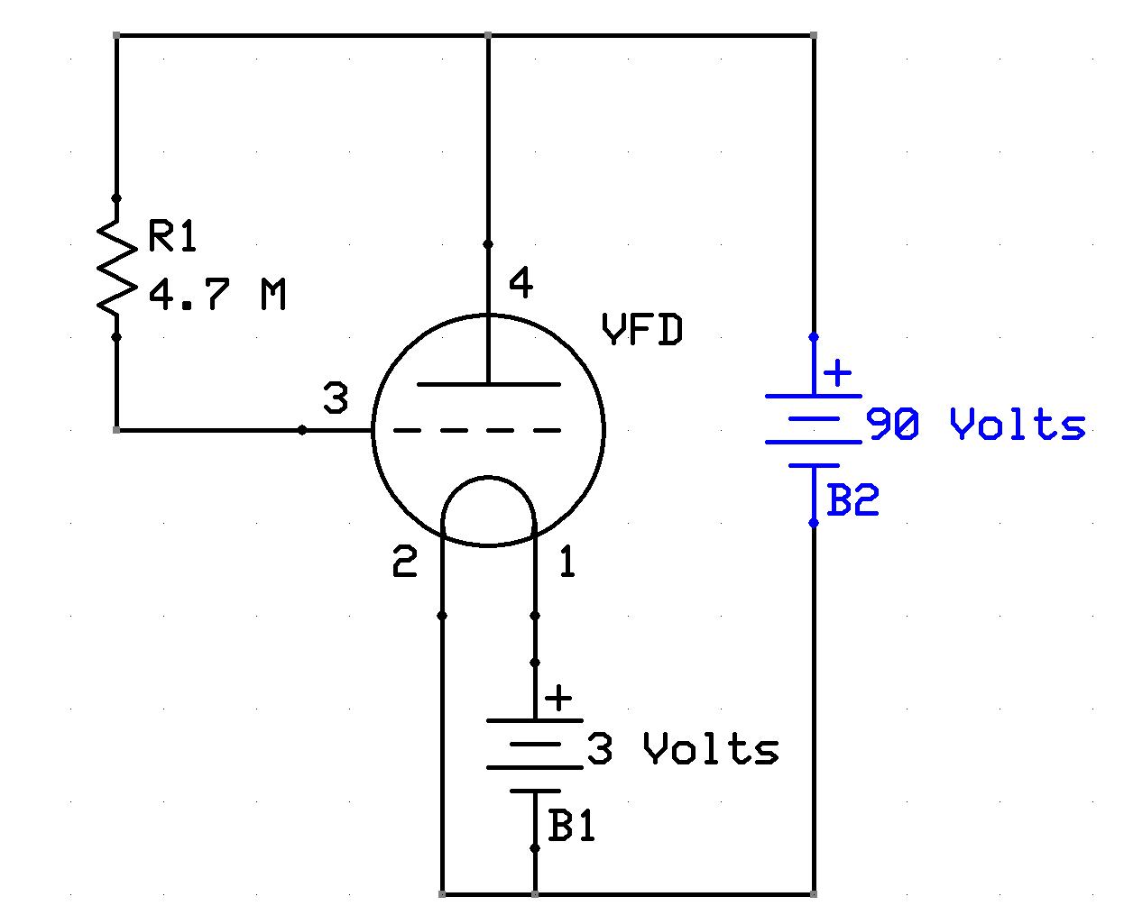
A circuit to light up the VFD
For the purpose of the experiments to follow, the final preparatory step is to use a soldering iron and some wire to connect all of the anodes together. Likewise, we must connect all of the grids together. This leaves a VFD with what amounts to four terminals: two filament terminals, one "super" grid terminal (the sum of all grids), and one "super" anode terminal (the sum of all anodes). In this "super" configuration, a positive high voltage applied to the "super" anode (with the 4.7 megohm resistor connected to the "super" grid) should light up all of the display features simultaneously.
The VFD Amplifier
One of the first observations I made occurred after I had lit my VFD in the "super" configuration. I broke the anode connection and inserted a high-impedance headphone into the circuit. I lifted the grid terminal and allowed it to "float." Immediately, the headphone was filled with a deep 60-cycle buzz—the kind one hears if the patch cord for a guitar amplifier is left dangling. It was obvious that the VFD was functioning as an audio amplifier. This prompted me to wonder if there was benefit in connecting this to a crystal radio.
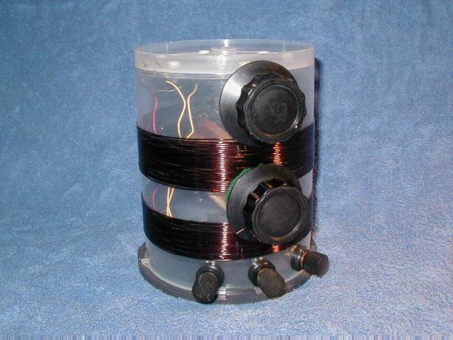
The CDROM radio
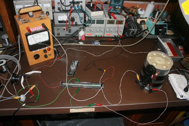
Amplifying the output of the CDROM radio. From left to right: Headphones, high-voltage power supply, low voltage supply, CDROM radio, and in the center, two different VFDs.

Simplified schematic for the CDROM radio and VFD amplifier. Click here to see it in higher resolution.
Above is an image of my "CDROM" radio, a crystal radio set based upon the container in which CDROMs are sold. I connected this radio to the VFD as represented in the simplified schematic above. Music came blasting through the headphones. Despite the fact that my antenna consisted of no more than 15 feet of wire thumb-tacked to the ceiling, the amplifier worked so well that the volume in the headphones was unpleasantly loud. During this period of experimentation, I made note of the following details:
a) The amplifier works when the audio signal from the crystal set is positive with respect to ground. It is almost completely non-functional when the detector diode is reversed and the audio signal becomes negative with respect to ground.
b) The VFD can function as both detector and amplifier. I verified this by bypassing the diode in the CDROM radio. Volume was reduced, but the amplifier still worked just fine.
c) The apparent gain of the amplifier is dependent upon the voltage applied to the "super" anode of the display. I have a variable high-voltage power supply. The amplifier provided useful amplification with an anode voltage of about 60 volts. At 90 volts, the amplifier worked much better. At 150 volts, the audio in headphones was so loud that music and speech could be heard with the headphones simply lying on the table.
d) Anode current never exceeded 6 milliamps. While this limits the VFD’s usefulness as a general purpose amplifier, it is more than up to the task of driving high impedance headphones.
e) A voltage gradient, apparently caused by the voltage drop along the filaments, causes a column of character blocks to assume an interesting triangular shape.
f) Strong local stations cause the display to modulate, i.e., become brighter and darker as the audio varies. This is not only interesting to watch, it is potentially useful as a tuning indicator.
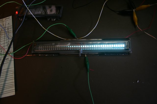
Image of operating display showing voltage gradient across the width of the display
g) A magnet applied to the face of the VFD causes visible distortions in the display and appears to have some affect on the gain of the tube, depending upon the magnet’s strength and orientation.
h) The planar construction of the tube makes it susceptible to nearby electrical noise. Noise in the audio channel can be greatly reduced by placing the VFD inside of a grounded metal box, or by laying a grounded metal plate upon the face of the display.
i) At one point, I replaced the headphones in the circuit with a small transformer, and used this to feed audio into my desktop computer to make a recording.
![]()
Audio transformer used to make recordings
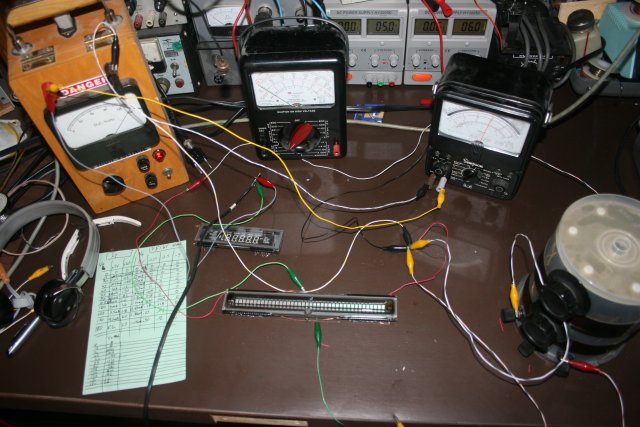
Image of characterization setup
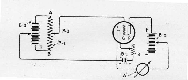
Characterization Schematic (From Vacuum Tubes in Wireless Communication, Bucher, 1919)
The great success of the VFD as an amplifying device prompted me to try to collect data to characterize it. To do so, I used variable power supplies to apply a series of voltages to the "super" anode and to the "super" grid. This, I did while simultaneously monitoring the anode current. This data was collected in a spreadsheet and then graphed using Excel.

Plate current as a function of plate voltage. Click here to see it in higher resolution.
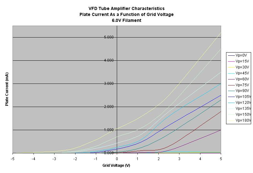
Plate current as a function of grid voltage. Click here to see it in higher resolution.
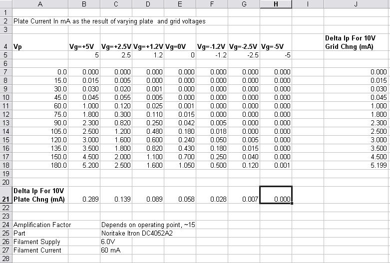
Tube characterization data. Click here to see it in higher resolution.
Conclusion
On this basis of this data, it appears that the particular VFD I was playing with, depending upon operating point, offers amplification on the order of 15 to 20 times—a respectable amount of gain.
While the triode vacuum tube and VFDs share common internal features, it doesn’t appear that VFDs can be wired to take advantage of grid-leak bias. And, despite the significant gain apparent in the VFD, I was not able to get it to function in a regenerative circuit. This shortcoming, however, might possibly be overcome with alternative biasing methods.
Samples of A.M. radio recorded with this equipment can be heard by clicking the following hyperlinks: smilesmilesmile instrumental
I have also prepared a short video, showing the VFD amplifier in operation, which can be found on Youtube here.
(This article was originally prepared for, and appeared in, the newsletter of the Xtal Set Society. Check them out!)
Document Revision 1, 11/30/08
Document Revision 2, 05/19/09