H. P. Friedrichs (AC7ZL) Homepage


Radio Room
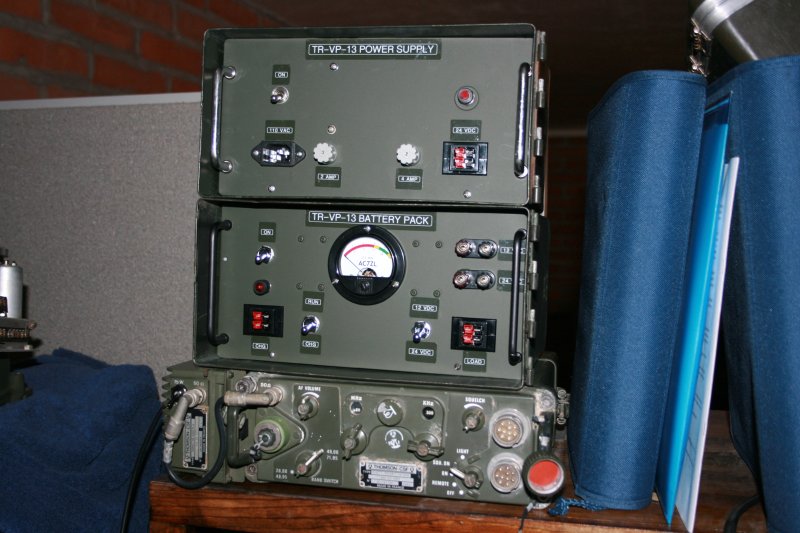
Power For the TR-VP-13:
Ideas for Homebrewed, "Military Style" Transceiver Power Supplies
Introduction
Several years back I authored two books, The Voice of the Crystal and Instruments of Amplification. These books deal with basic electronic principles and describe what some have called "extreme homebrew" projects. These projects include homemade radio components ranging from coils, variable capacitors, detectors, and headphones to experimental homebrew tubes and transistors.
It seems that one or more of these books made their way to the battlefields of Iraq, and into the hands of a serviceman deployed there. An email inquiry from this gentleman resulted in a dialog between us, which eventually developed into full-blown friendship. It also led to my receiving the gracious gift of a TR-VP-13, a receiver he had found in the field.
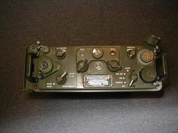
The TR-VP-13 is a battlefield VHF military radio, manufactured by Thompson CSF in France. My effort to understand, restore, and operate this radio are described in considerable detail in my article If Rigs Could Talk: An Iraqi Veteran Comes to the United States, which can be found on my web site. Once the radio was functional, I began to contemplate building some nice-to-have accessories for that rig. My first thoughts centered on power supplies, and this led to two projects I am about to describe.
Needless to say, I would expect this article to be of use to the owners of TR-VP-13s and probably to the owners/collectors of portable military radio gear in general. However, given the nature of what I've done and how I did, I suspect that there is a larger audience of radio amateurs who might be interested in some of the ideas presented here. Everyone needs power, right?
A Base-Station Power Supply
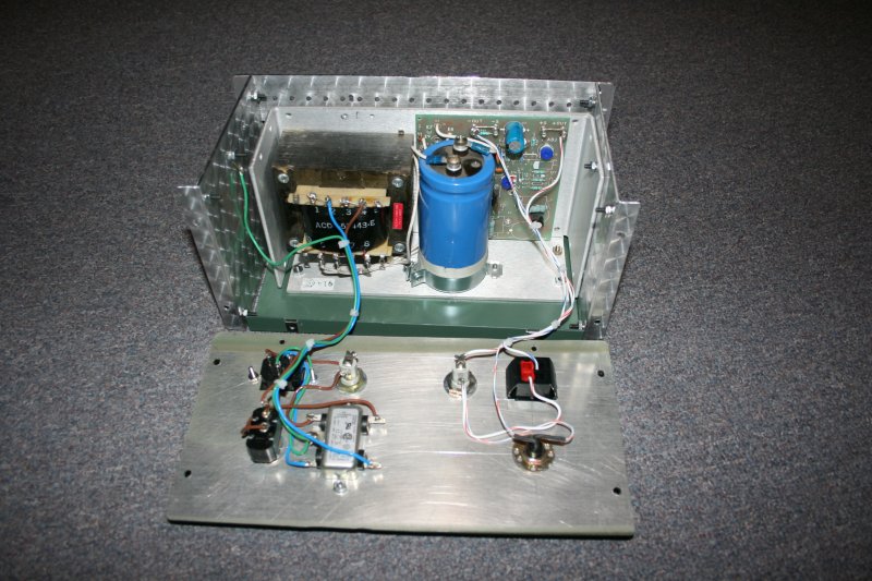
The TR-VP-13 (and many other military radios, from what I gather) needs a 24-volt DC power source. While I didn't have any documentation spelling out the radio's power requirements, I knew that the set is capable of transmitting up to 15 watts when the outboard linear amplifier is kicked in. I figured I'd need a supply capable of delivering at least twice that much power, and so I began to search for a suitable transformer.
What I stumbled upon, instead, was a used 110-volt AC input, 24-volt regulated DC output, open-frame power supply. The supply was rated at 4.8 amps, more than sufficient for my purposes. It appeared in a box at a local hamfest, and became mine for a few dollars.
A Box To Put It In
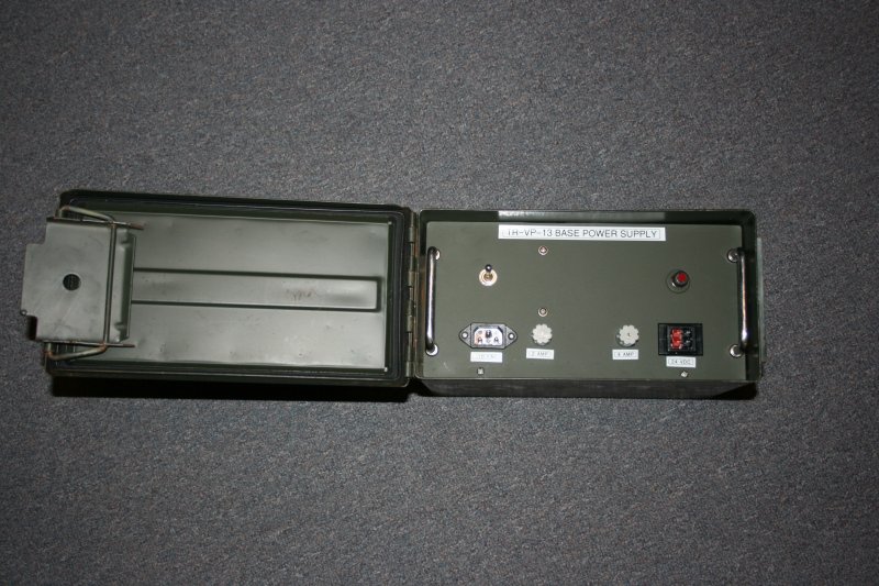
My next concern was to find or fabricate a suitable enclosure. There are endless options here, as evidenced by the wide variety of containers that hams have pressed into service to house their homebrew equipment. My thought was that the TR-VP-13 was a military radio, and that an appropriate power supply should have a military-hardware look about it. I wanted something tough, and something that might look as though it had been issued with the radio. I made a trip down to our friendly neighborhood army/navy surplus store and shuffled through the store looking for ideas. When I came upon the store's stock of empty ammunition boxes, I knew I had hit pay dirt. (The image below shows an example.)
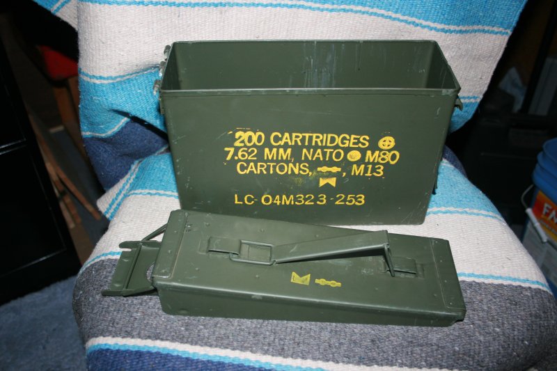
I am convinced that it is impossible to own just one ammo box. Once you've purchased one and discover its utility, you have to obtain more. I've seen them used to store ammunition, pistols, fishing tackle, nuts and bolts, lawnmower parts, money, important papers, and a hundred other things. These boxes are fabricated from rugged steel, and you can bet that they will take a beating. The lids are fitted with gaskets, so when the boxes are closed, they are watertight. Yet, when opened, it is possible to remove the lids completely�a nice feature when you want them out of the way. Finally, they are painted in that classic shade of "olive drab." I decided that a large ammo box had all the attributes of an ideal enclosure for my power supply. I selected and purchased a box formerly used to house 50-caliber rounds.
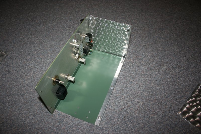
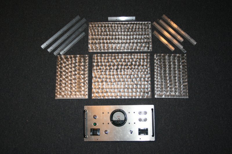
An Aluminum Chassis
The next step was to mount the power supply assembly into the ammo box. The question was, "How?" I couldn't come to terms with the idea of drilling holes through the sides of the box, as this would defeat the whole point of having a gasket in the lid. I decided instead to fashion an aluminum chassis that would slide into the ammo box.
I fabricated my chassis from scrap aluminum, junk that I had collected over the years. I sized and cut rectangles to form a floor plate, sides, a back plate, and a front plate. The plates were joined with sections of one-half-inch aluminum angle, purchased from the hardware store. While I could have assembled the chassis using rivets, I decided to employ 6-32 bolts, nuts, and lock washers. I felt that this would result in a stronger chassis. Just as important, in experimental projects like this one, nuts and bolts allow for the possibility of changing one's mind.
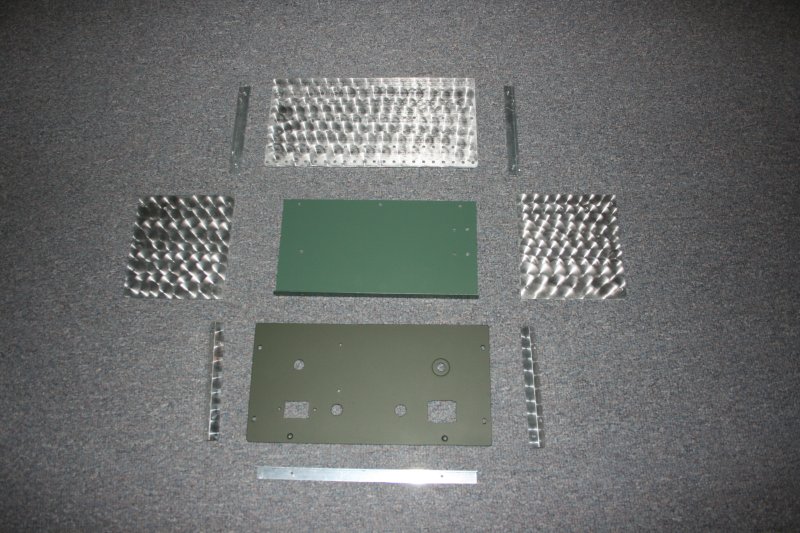

I've already alluded to the fact that the material used to fashion my chassis was salvaged from scrap aluminum. Much of it was scratched and dinged. Obviously, the appearance of these internal parts has no effect on the overall functionality of the device, but I decided that aesthetics matter to me and that it was worth it to try to clean things up a bit.
To accomplish this, I chucked a flat-headed bolt into my drill press. I wrapped the head of the bolt with a synthetic scouring pad, and secured it in place with a piece of wire. I turned on the drill press, brought the rotating pad down onto the surface of one of my aluminum parts, and produced a nice circular swirl pattern in the metal. I relocated the whirling pad and brought it down on the metal again. The method to my madness was to begin at one corner of the work piece and produce a series of swirls, each partially overlapping the prior, stretching from one end of the work to the other. That completed, I began a second line of swirls, followed by a third. Parts that are covered with this pattern take on a pleasing jewel-like appearance. Held at arms length, the pattern almost completely masks any scratches or other defects in the metal.
With regard to my technique for applying the jewel pattern, a few comments are in order. First, make certain that you wear eye protection. Leather gloves might not be a bad idea either. Light pressure from the drill press, applied for a longer period, seems to produce nicer swirls than heavy pressure applied for an instant. Of course, it takes proportionately longer to complete a piece of work. Finally, I have experimented with different abrasives including both synthetic scouring pads and steel wool. Steel wool is cheaper, cuts faster, and lasts longer than synthetic pads. On the other hand, synthetic pads seem to produce cleaner and more uniform swirls.
You will note that I have not discussed any specific dimensions for my chassis, and this is on purpose. First, there are countless ways to arrange the elements of a chassis, my design being but one example. Second, there seems to be an infinite variety in ammunition boxes. I'd go so far as to say that the chassis dimensions are not at all critical, provided that you understand certain factors and account for them.
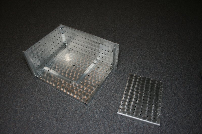
Point 1: The girth of the chassis needs to be somewhat less than the interior dimensions of the box, so as to allow a sliding fit.
Point 2: By definition, a chassis fabricated from flat plates of aluminum joined with aluminum angle will have sharp, 90-degree edges. However, the edges and corners of ammunition boxes are radiused, i.e., they have a curve to them. It should be obvious that sharp edges on a chassis will not slide comfortably into the radiused corners of the ammo box.
The solution to this problem is fairly simple. I began by sizing and cutting the front and back panels to precisely fit the mouth of the box. I used a file to radius the corners of these plates as necessary. The sides of the chassis can be dimensioned to the full height of the box. The floor plate, however, is cut to be somewhat narrower than the interior of the box. When the chassis is assembled, the net effect of all this is to "float" the chassis between the walls of the ammo box.
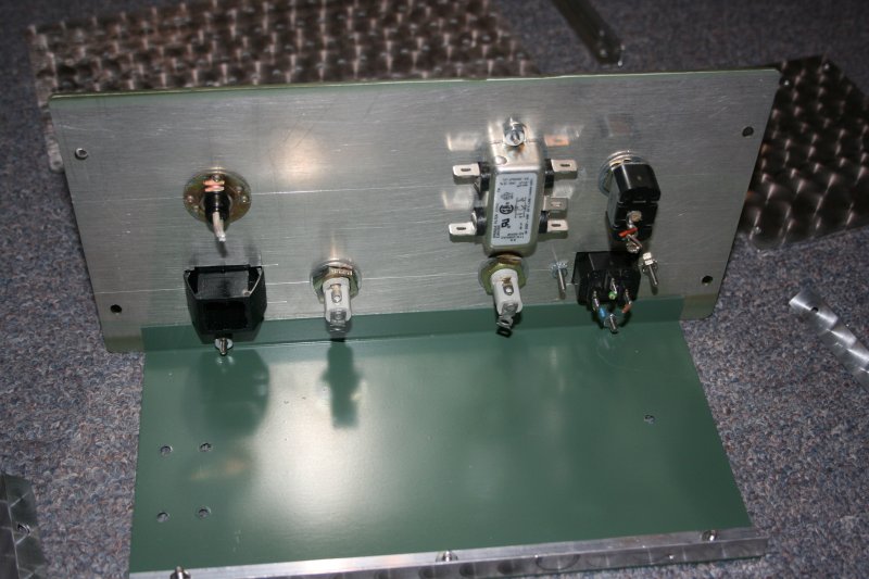
Point 3: The chassis should be dimensioned such that, when the chassis is installed in the ammo box, the front plate is recessed and lies below the mouth of the box. The reason for this is that the front panel is the mounting point for switches, lamps, connectors, and other items that must protrude from the surface of the plate. If the front plate is not sufficiently recessed, there will not be the clearance necessary to close the ammo box's lid.
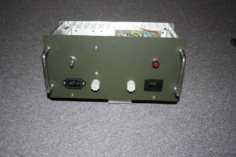
Speaking of the front plate, one of its prominent features in this design is a pair of U-shaped handles. The purpose of these handles transcends good looks and is actually three-fold. First, the handles provide a convenient means by which the chassis can be withdrawn from the ammo box. Second, the handles offer some mechanical protection to the switches, lamps and other components in the event that the chassis or open ammo box should fall face-down onto some hard surface. Finally, the handles are sized (and the chassis dimensioned) so that the box's lid contacts the handles when the lid is in place. This secures the chassis further, and prevents it from sliding forward and backward during transit.
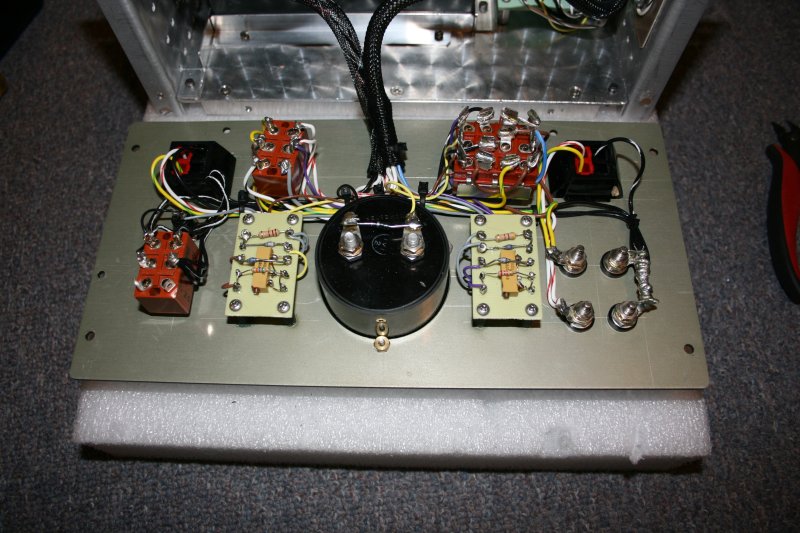
Once the front plate had been drilled and machined to accommodate switches, fuses, and connectors, the plate was scoured lightly with steel wool and then cleaned. Using spray paint, I laid down a primer coat, followed by four or five coats of olive-drab spray paint. The olive-drab paint was purchased at a local sporting-goods store.
Legends for the switches and other items on the panel were created with a P-Touch � label-maker.
Base Station Power Supply Wiring Details
The internal wiring for the base station supply is depicted in the schematic here. One-hundred-twenty-volt AC line current is delivered to the power supply through a PC computer-type IEC power cord. The cord mates with a standard C14 chassis plug, mounted on the supply's front panel. Inside the chassis, line current passes through a protective fuse and through a Sprague line filter. From there, the current is delivered to the input side of the 24-volt regulated DC power supply assembly.
The output of the supply is protected with a second fuse, lights a pilot lamp to indicate output power is present, and is eventually delivered to a front-panel connector composed of four Anderson Powerpoles.
Powerpoles are well-regarded by most hams I've spoken with, and these connectors have emerged as the basis for a "standard" low-voltage interface specified by many emergency communications organizations like. I was inclined to use Powerpoles to connect the TR-VP-13 to my base supply, but I was concerned about creating a potential danger where a 12-volt device might accidentally be connected to a 24-volt supply.
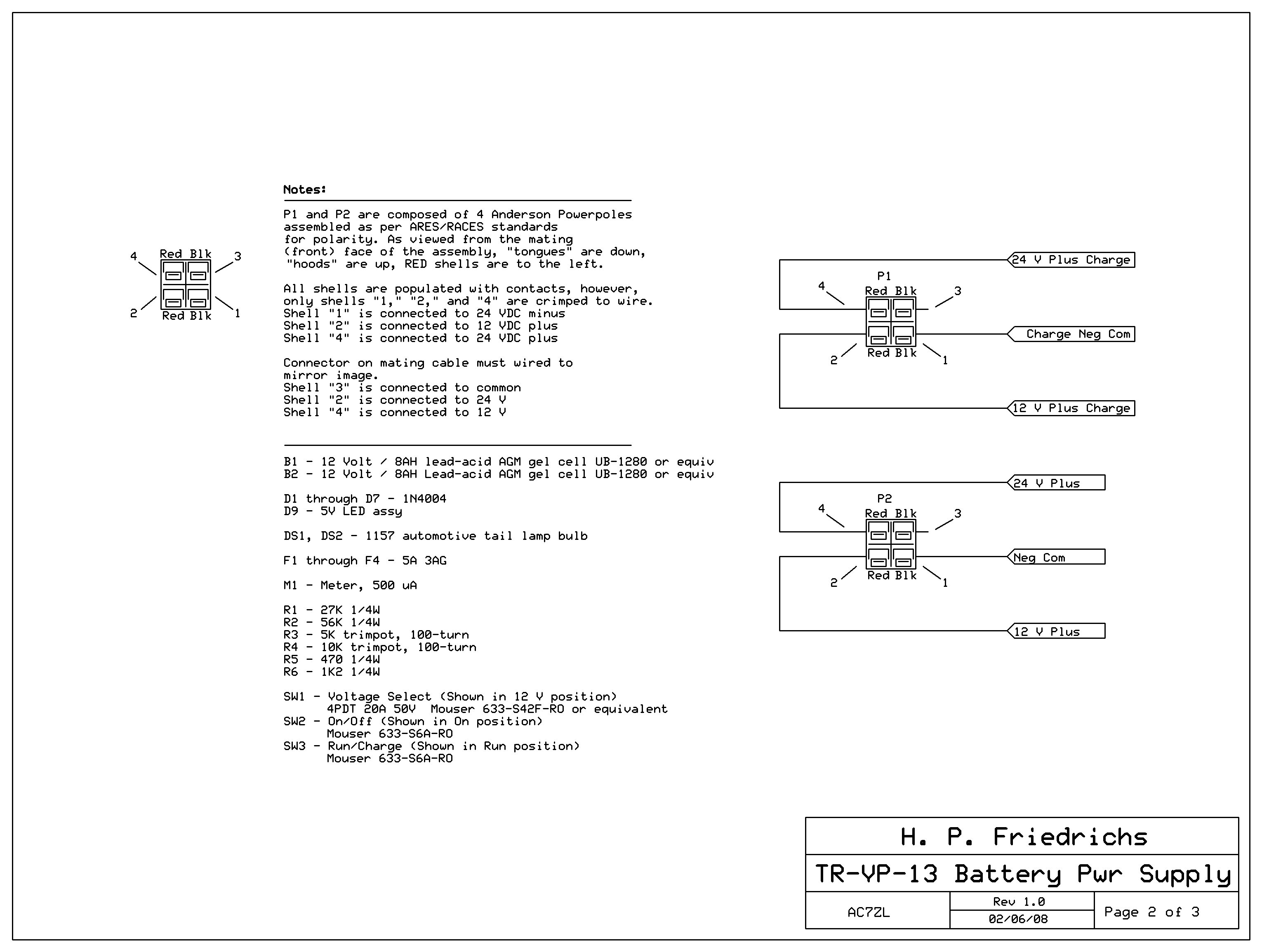
To preclude this, I developed my own 4-terminal standard, which is a superset of the ordinary RACES/ARES specification. My standard has the potential to deliver both 12 and 24 volts (if these voltages are available� in this case my TR-VP-13 base supply delivers only 24 volts.) Thus, it is backward-compatible. At the same time, it addresses and reduces the likelihood that a given radio will be blown up by the application of inappropriate voltages.
A further benefit of my standard is that it can utilize the locking 4-terminal connector bodies that Anderson offers. These allow the fabrication of cables that click and lock onto their mating connectors, eliminating the tendency for power connectors to come apart and for cables to unplug themselves. This is a well-known problem associated with the RACES/ARES 2-terminal standard.
Next: A Battery Box
The base station supply I've just described looks good and works even better. That said, the TR-VP-13 was really intended to be a mobile radio. Unfortunately, the radio's 24-volt requirement precludes me from powering it with any typical 12-volt source (like the cigarette lighter jack in my truck), so if I wanted to use the radio in a mobile fashion, I would have to rig up a battery pack for it. I figured that a couple of small 12-volt AGM gel batteries wired in series would work nicely.
Now, building the enclosure for the base supply wasn't rocket science, but I discovered that doing a nice job does involve a fair amount of labor. A similar amount of labor would be required to build the enclosure for a military-style battery back. In principle I wasn't opposed to investing this effort, but I did realize that a 24-volt pack would be of little use to me aside from its application to the TR-VP-13. All of my other radio gear is 12-volt equipment.
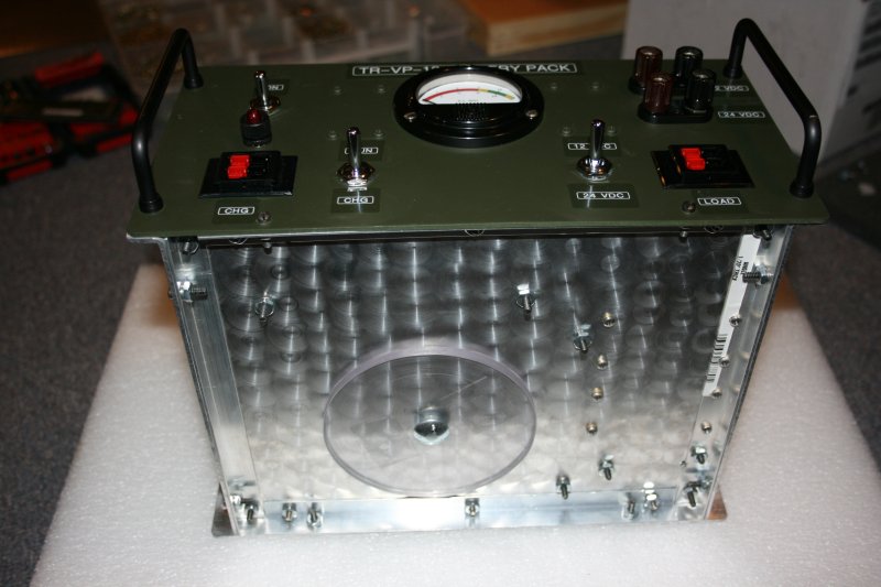
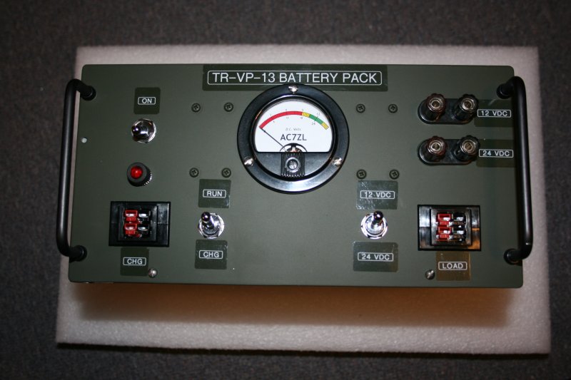
This prompted me to think about a design in which the battery box would be configurable. Throw a switch one way, the pack is wired for 24 volts. Throw a switch the other way, and its wired for 12 volts. An arrangement like this would make the battery box flexible, and of much greater use to me.
A Chassis For The Battery Box
The chassis that I designed for the battery box is similar to the chassis I built for the base supply, though there are minor differences. The 1/2-inch aluminum angles used to anchor the floor plate in the base station supply chassis are located inside the chassis. This allows for the maximum possible interior space in the chassis, and this was required to get the regulated power supply assembly to fit. In the case of the battery box chassis, the 1/2-inch angle stock anchoring the floor plate is located beneath the plate, outside of the chassis' interior. This reduces the interior height of the chassis by about 9/16", but provides a "hollow" into which bolt heads and nuts can protrude.
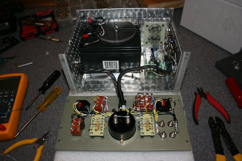
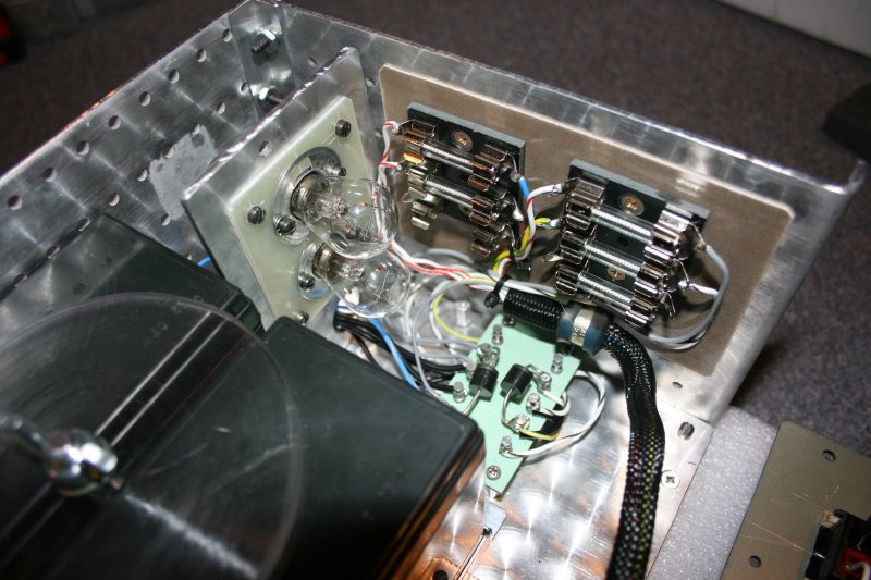
The main challenge in building the chassis for the battery box was arriving at a suitable means for anchoring the batteries. My solution was simple, but effective. First, I attached some lengths of 1/2-inch aluminum angle to the floor plate to create a "tray" in which the batteries would sit. This tray confines the batteries and prevents them from sliding side-to-side.
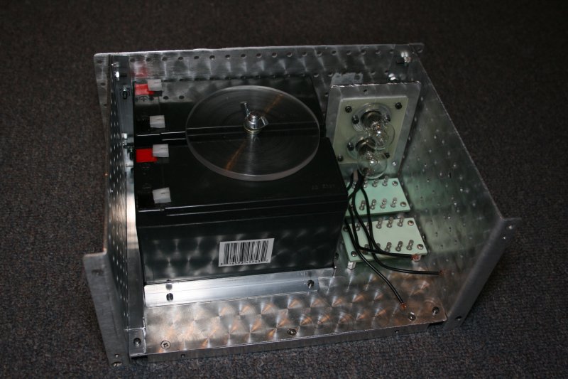
The battery retainer consists of a long, 5/16-inch carriage bolt, two acrylic disks about 3-1/2 inches in diameter (each with a hole in its center), a steel washer, and a wing nut. I arranged the batteries so that they stand, side-by-side, with a gap between them. I drilled a hole through the floor plate, in the gap between the batteries.
One acrylic disk is slid onto the bolt like a giant plastic washer. The bolt is inserted from beneath the floor plate, rises upward between the two batteries, and is fitted with another acrylic disk. Finally, I added a steel washer and the wing nut. When the wing nut is tightened, the batteries are clamped to the floor plate and will not move. I should mention that I took the added step of lining the floor of the tray with a sheet of complaint, foam rubber. This is intended to offer some shock protection to the batteries in the event of a fall.
A Look At The Battery Box's Circuitry
The circuitry in the battery box is much more complicated than the wiring in the base station supply, but is easily understood if considered in terms of its functional blocks. A look at the schematic diagram reveals a portion of the circuitry associated with the batteries, a portion associated with charging, and a portion associated with metering. The schematics can be found on , Sheet 1, Sheet 2, and Sheet 3.
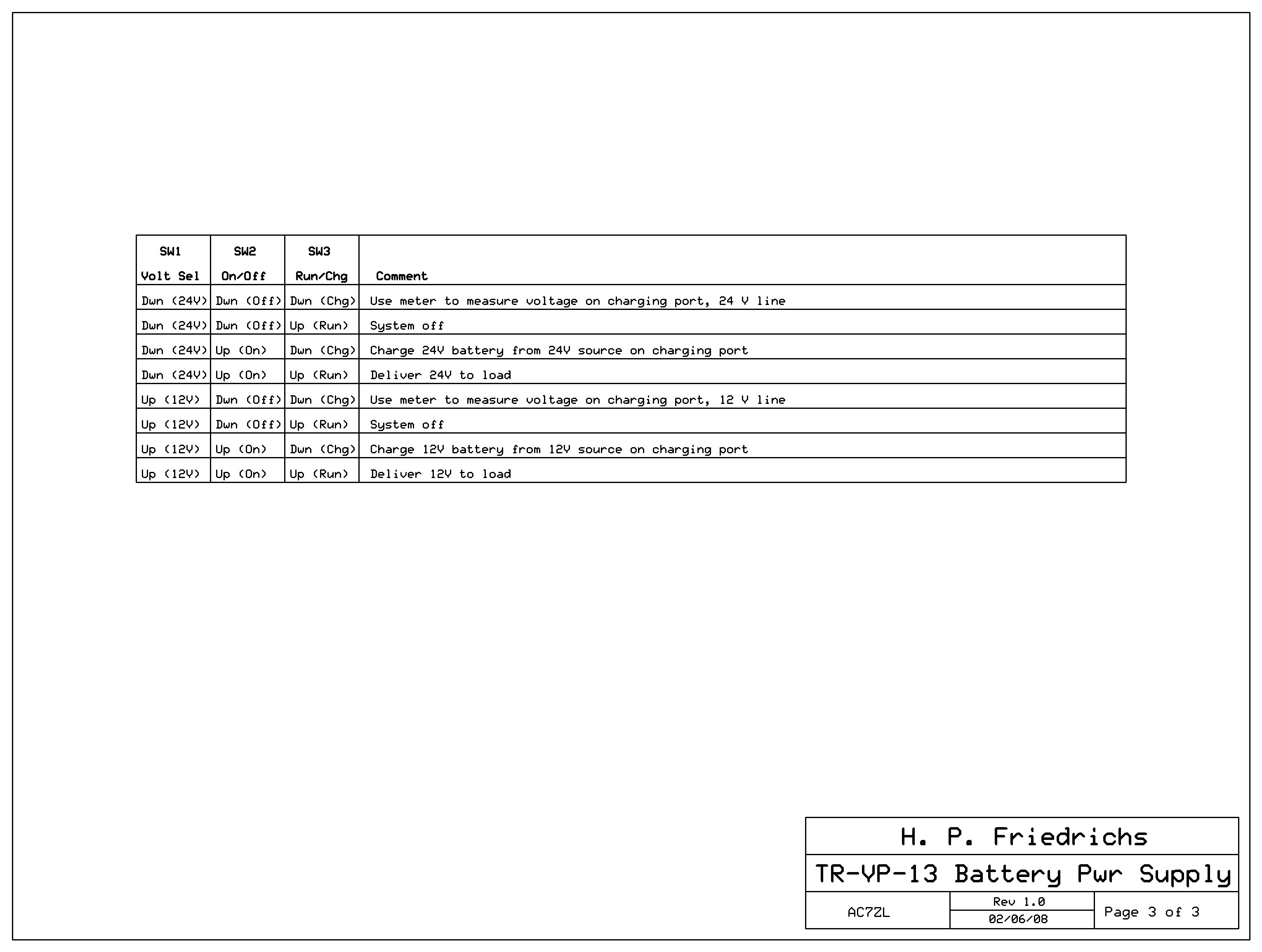
Let's discuss the battery portion of the circuitry first. This section is composed of switches SW1 and SW2, fuses F1 and F2, and two batteries, B1 and B2. SW2 is double-pole, double-throw (DPDT), and amounts to on/off switch. When it is open, the negative leads of both batteries float, making any flow of current impossible. When SW2 is off, you can neither charge the batteries, nor draw from them.
Fuses F1 and F2 provide short circuit and overload protection. If something goes wrong, the fuses will open, and the batteries will be disconnected.
SW1 is a four-pole, double-throw (4PDT) switch. It performs the magic of configuring the box either for 12 or 24 volts. Depending upon how it is set, it will wire the batteries either in parallel or in series.
Switch SW3 is a DPDT switch that controls whether the box is in "run" or "charge" mode. In "run" mode, the batteries are connected to a 4-terminal bank of Anderson Powerpoles (P2), configured to my standard (described earlier.) This allows the batteries to deliver power to an external load, like the TR-VP-13 or other radio gear. When SW3 is thrown to the "charge" position, the batteries are disconnected from P2, and are instead connected to the box's charging circuitry.
I spent a fair amount of time contemplating what the battery charging circuitry should look like. I could have incorporated some kind of solid-state charge controller, perhaps based on op-amps or even a microcontroller, but I opted instead for a design that is much simpler.
The charging circuit consists of fuses F3 and F4, lamps DS1 and DS2, a 5-volt LED lamp (D9) some current limiting resistors, and a set of steering diodes, D3 through D6. Power for charging the batteries enters the box through a bank of four Anderson Powerpole terminals, designated P1.
Since the batteries can be configured by SW1 to produce either 12 or 24 volts, it follows that the batteries can be charged either with a 12 or 24-volt source. The charging circuit reflects this idea with two separate charging paths. The specific circuitry involved in 12-volt charging is more-or-less duplicated for 24-volt sources, so in general, any comments made about one applies to the other.
In either case, charging current flows through a fuse (either F3 or F4), through a lamp (either DS1 or DS2), through a 6-amp silicon diode (D3 or D4), and on to the batteries via SW3. The fuses protect the external energy source from damage in the event that short circuit develops inside the battery box. Diodes D3 and D4 prevent interaction between 12 and 24-volt charging sources. More important, they prevent the batteries from discharging backwards into the charging current source. Now, what is the point of the lamps?
DS1 and DS2 are dual-filament automotive tail lamp bulbs, number 1157 to be exact. They are installed to exploit the fact that the resistance of lamp filaments increases as the lamp begins to light. Because of this, they act as simple current regulating devices.
Note that there is a subtle difference between the wiring for DS1 and the wiring for DS2. DS2 is part of the 12-volt charging circuit. If we assume a dead (0-volt) battery, a 12-volt charging current source will cause 12 volts to appear across DS2. No problem there. However, a 24-volt charging source driving into dead battery will cause 24 volts to appear across DS1. To prevent DS1 from being burned out (remember, it's a 12-volt automotive lamp) the two filaments in DS1 are wired in series. By the way, the use of the DS1 and DS2 in this manner requires that the sockets for these lamps be isolated from ground.
D9 is a 5-volt LED lamp assembly. It lights whenever a charging current source is present on connector P1. Diodes D5 and D6 prevent interaction between 12 and 24 volt sources, and resistors R5 and R6 provide current limiting.
The metering circuit in the battery box is dual range, 0-15 volts, and 0-30 volts. It is based on a 500 microamp meter I happened to have lying around
. 
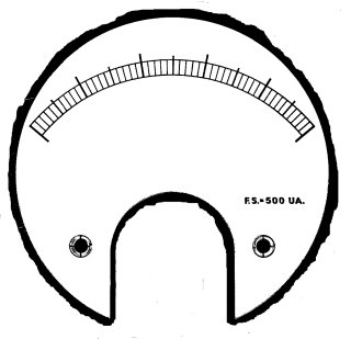

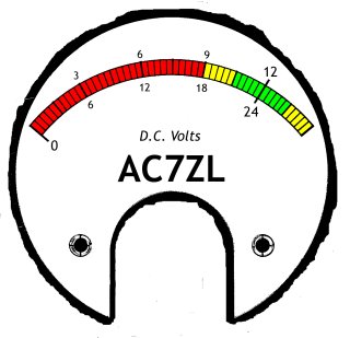
The meter scale was customized for this application. I dismantled the meter, scanned its face on my computer scanner, and used Gimp to create a new scale, complete with color and my call sign. I then printed the new scale on photo paper, used spray-on contact cement to bond the paper to the old meter scale, and resinstalled it in the meter houseing.
Diode D1, resistor R1 and R3 comprise the ranging and calibration circuit of 0-30 volt measurements. Diode D2, resistor R2 and R4 comprise the ranging and calibration circuit for 0-15 volt measurements. The meter range is selected by SW1.
Conclusions
All engineering exercises boil down to one thing: compromise. Among an engineer's greatest challenges is to balance desired features (some of which may be mutually exclusive) against cost. In this regard, both the base station supply and the battery box I've just described fare well.
There is something to be said for aesthetics. The supplies I've built look as though they belong with my military radio gear.
Both the base station supply and the battery box are built of inexpensive materials. Ammo boxes are ubiquitous and cheap. I've paid as little as two dollars for a box, but no more than ten. One can make extensive use of scrap aluminum, recycled fasteners, and recycled electrical parts, as I did.
I suspect that if either my base station supply or my battery box fell out of the back of my pickup truck, they would be dented and abraded, but the equipment would remain safe. I have no doubt that a small car could actually drive over my enclosures, and while the boxes might be deformed, their contents would remain functional. I am also confident that this equipment could survive water immersion for long periods under several feet of water (this has been confirmed in the shallow end of my swimming pool.) Finally, metal is immune to UV exposure, and doesn't become brittle on exposure to the cold.
The battery box can be set up to deliver 12 volts for common ham gear. Throw a switch, and it will provide 24 volts for military radios.
The built-in analog meter in the battery box provides continual indication of battery health.
The batteries can be charged with a 12-volt source and discharged at 24 volts, or charged at 24 volts and discharged at 12. This unusual flexibility may be a plus in emergency situations. It also gives the base station supply added utility as a charger for the battery box.
If the battery box is switched off, but set to the charge position, the meter will indicate the voltage present at the charge port. This is useful for verifying the suitability of a charging current source before applying it to the batteries. If a cable is fashioned for P1 that is terminated with alligator clips or probes, the battery box can be used as a simple, emergency voltmeter.
Since design is about compromise, there are some down-sides to what I've just described, primarily associated with the battery box.
First, it is not possible to charge the batteries in the battery box and run a load at the same time. I don't consider this a big deal. If it proves to be a problem, it can be addressed by fashioning a "Y" shaped cable to couple the base station supply to the battery box and TR-VP-13 at the same time.
Second, the charging circuitry is primitive and will not tolerate large excursions in charging voltages. This is not necessarily a problem. I anticipate charging the battery box at home with the base station supply. The most likely source of charging voltage in the field will be an automotive cigarette lighter jack. Both sources are easily managed by the circuitry described.
Finally, the charging port P1 and the output port P2 are keyed the same way, and it is conceivable that someone might accidentally exchange cabling. Fortunately, If a load cable is accidentally connected to the charger port, the load simply won't power up. Neither the battery box nor the load will suffer any damage.
It is true that a charging cable attached to the output port P2 would become energized, but under certain circumstances, this "fault" might be considered a feature. For example, imagine a charging cable terminated with a cigarette lighter plug. Under normal circumstances, it is connected to P1 and used to charge the battery box from an automobile's lighter jack. Now imagine a situation where the same vehicle has been parked and the headlights left on. Its battery has been drained and weakened, and the engine won't start. If the battery box charging cable is moved from P1 to P2, (and SW3 is thrown to the "run" position) it is possible that the battery box might deliver enough energy back to the vehicle battery to allow the engine to be started. This is the idea behind some of the compact battery boosters available commercially.
This leads me to a final comment about the use of ammunition boxes for equipment housings. I have proposed this idea on Internet forums before, particularly in the context of their use as containers for emergency power and communications gear. This has triggered complaints that steel boxes are "too heavy" and thus unsuitable. True, they tend to be heavier than comparable plastic containers, but weight is just one consideration in a list of many. In an emergency, I'd rather lug a "heavy" piece of gear to my operating position, confident that it will work when uncrated, as opposed to transporting a "light" piece of gear and then deal with the consequences of smashed or water-damaged electronics.
Document Revision 1, 02/19/2008
Document Revision 2, 03/04/08