H. P. Friedrichs (AC7ZL) Homepage


Radio Room
Building the "Pipsqueak" Receiver
Introduction
One fall evening about ten years ago, I was inspired to tinker with some old radio parts I had accumulated in a box. I found a ten or twelve-inch-square slab of plywood lying about, and using some wood screws, I secured to its surface a tube socket and a couple of old variable capacitors. A row of screws, partially driven into the wood, served as battery and phone terminals. I wound tuning and reaction coils on a chunk of cardboard mailing tube, and then used a fistful of alligator leads to wire everything up. The circuit was of the classic regenerative type, and wiring this receiver took all of two minutes.
The radio was grounded to the cover screw of a nearby wall outlet, and the antenna was nothing more than a fifteen or twenty-foot length of wire which had been thumb-tacked to the ceiling of the garage. I inserted a #27 triode into the tube socket, and hooked up a set of batteries The headphones screeched. I fiddled with the controls, and my phones suddenly filled with strange music and dialog about... vampires! Puzzled, I waited for station identification and discovered that I had been listening to a radio broadcast of Bram Stoker's Dracula, broadcast from a BBC station, more than 5000 miles away. If that isn't magic, nothing is.
It's entirely fair to say that there is no radio circuit, using so few components, that can outperform a regenerative receiver in terms of sensitivity and selectivity. Regenerative receivers are simple and fun to build.
Building Something From Nothing
There is a certain pack-rat behavior associated with many engineers and ham radio folks, and I readily admit my guilt in this regard. Most of us have well-developed junk-boxes. However, my own propensity to collect junk has nothing to do accumulation for the sake of accumulation. Rather, I would argue, my eyes see potential in things others are willing to discard. It bothers me to see a resource go into a landfill when I know I could make something useful out of it. In my world, no stereo, computer, television, or appliance, for example, should end up in a garbage can until it has been inspected for and stripped of its bounty of useful pieces and parts.
There is little point to this activity if the material thus collected is not eventually put to good use. In this article, I describe a project I call the "Pipsqueak" radio, a simple regenerative receiving set fabricated from some of the odds and ends I have collected over time.
The "Pipsqueak" Receiver
How The Pipsqueak Works
The schematic diagram for the Pipsqueak can be found here.
Radio signals are directed from the antenna to a tuning circuit composed of the coil L1 and capacitors C1, C2 and C3. The combination of these parts comprise the Pipsqueak's tuner. C1, C2, and C3 are adjustable and are all attached to the same shaft. As the tuner shaft is adjusted, the values of C1, C2, and C3 change. This changes the resonant frequency of the tuner, that is to say, the frequency at which the Pipsqueak will "listen."

The Pipsqueak schematic. Click on the image for better resolution.
Energy from the station of interest is applied to the control grid of a 1T4 pentode vacuum tube, which functions as an amplifier and detector for this receiver. Resistor R1 and capacitor C4 comprise something called a shunt "grid leak," the purpose of which is to accumulate a charge in order to bias the tube for proper operation.
An amplified copy of the signal emerges from the IT4's plate at pin 2. This is applied to coil L2, sometimes referred to as a "ticker" coil. L2 is located in close proximity to L1. As energy passes through it, a magnetic field created by L2, which transfers some of that energy back to coil L1. This is the feedback path that makes regeneration possible. Signals amplified by the tube and sent back to its own input can circulate through the tube again and again, providing additional gain.
The effects of excessive feedback are well known to anyone who has observed a stage performer who has carried a hand-held microphone too close to the P.A. speakers. Sound enters the mike, is amplified, and then it blasted by the speakers. The speaker's sound reenters the microphone, where it is amplifier further, and exits the speakers again. If the energy of the circulating tone continues to build, the end result is a grating screech or howl.
Likewise, too much regeneration makes the Pipsqueak "squeak," which is not only unpleasant, but can actually degrade the sensitivity of the set. What is needed is a mechanism for throttling or controlling the extent to which the tube can amplify. This functionality is implemented with resistors R2, R3, and capacitor C7. Adjustment of variable resistor R2, called the "reaction" or "regen" control changes the voltage applied to the 1T4's screen grid. The effect of this is to modify the gain of the tube.
The output of 1T4 also contains audio information, which was extracted from the radio signal. This is applied to a transformer, T1, and eventually to the headphones, where the station can be heard. Since two kinds of signals are being amplified by the tube simultaneously, both radio signals and audio, some circuity must be used to separate them. Capacitor C5 and radio frequency choke L3 perform this function.
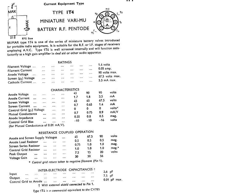
As already mentioned, the heart of the Pipsqueak is the 1T4. This is a seven-pin glass vacuum tube designed for service in battery-powered receivers. The filament of the tube is rated for 1.4 volts DC. Drawing only 50 milliamperes, the tube can be lit with ease from a single D-sized flashlight battery. By convention, this is called the "A" battery or "A" supply.
The plate voltage specification for the 1T4 is 90 volts DC. While the Pipsqueak works best with a plate voltage near 90 volts, it was actually designed for operation at 45 volts. Either voltage is easily supplied by stringing 9-volt transistor batteries in series to achieve the desired total. By convention, this is referred to as the "B" battery.
One of the advantages of experimenting with the 1T4, then, is that it allows for experimentation with vacuum tube technology without exposure to the potentially lethal voltages required by other types of tubes or their circuits.
The Pipsqueak's Chassis
Regenerative receivers can be finicky. Regenerative radio chassis should be robust and structurally sound, because flimsy physical construction allows for subtle movement in critical components like the tuning capacitor and tuning coil. This can affect the stability of the circuity, resulting in a radio that doesn't hold its tune, or is prone is screaching or squeaking when it shouldn't. Regenerative receivers also require a good internal electrical ground, and the front panel should be metallic, or least shielded. That shield or panel should be grounded as well. Failure to provide adequate shielding and grounding can result in a radio that detunes simply because the operator has placed his hands near the controls.
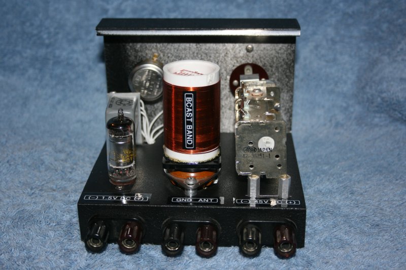
A rear view of the Pipsqueak. Note the terminals for power, antenna, and ground.
The Pipsqueak's chassis is made from aluminum scrap. It began life as the housing of a discarded industrial instrument. The housing was composed of two C-shaped aluminum extrusions, which together, formed the top, bottom, and sides of the instrument. When the instrument was discarded the extrusions were saved. One extrusion became the chassis, the other the front panel. Needless to say, some work with a saw was required to encourage a cooperative fit. The front panel is secured to the chassis with a couple of 6-32 screws, lockwashers, and nuts.
The chassis meets all requirements for rigidity and robustness. It's aluminum content is highly conductive, resulting in a well-grounded chassis and a well-shielded front panel. The black finish, by the way, is the original paint.
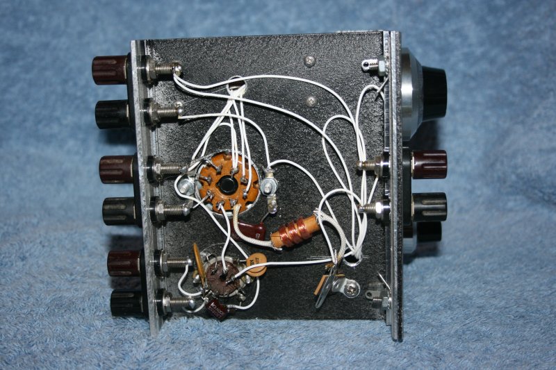
A view of the underside of the chassis.
Connections are made to the Pipsqueak through binding posts, which are mounted through holes drilled in the aluminum chassis. These posts were all salvaged from discarded electrical equipment. Two binding posts at the front of the radio allow for the connection of headphones. Three pairs of binding posts at the rear of the radio allow for the connection of the "A" battery, the "B" battery, and an antenna and ground.
The Vacuum Tube
The 1T4 tube was a gift from a friend, but this tube, and similar battery-operated tubes, can be located and ordered through vendors on the Internet. The tube socket was used, and salvaged from discarded equipment. Electrical characteristics for this tube can be found here and here.
The Variable Capacitor
The tuning capacitor is new-old-stock, and was purchased through an online auction site for a few dollars. Similar parts show up with regularity. Other sources include hamfests, or suppliers of vintage radio parts. Thrift store, Salvation Army, or garbage-can stereos are a source of similar components.
I really like the capacitor I used because it includes some gearing, which reduces the rate at which the capacitor blades move. This makes tuning much less "touchy." It was originally designed for printed circuit board mounting, as evidenced by four post-like feet, clearly intended to be soldered into holes in a printed circuit board. I found that with a little force, I could screw a short, threaded, standoff onto each post, which not only extended the feet but gave me a way to bolt the capacitor to the chassis. To assure that the capacitor's feet would never pull out of the standoffs, I applied a few drops of epoxy before forcing them together.
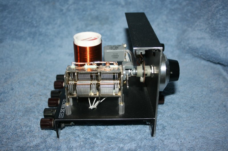
The Pipsqueak's tuning capacitor. Note that it has multiple sections which can be accessed through the tuning coil socket.
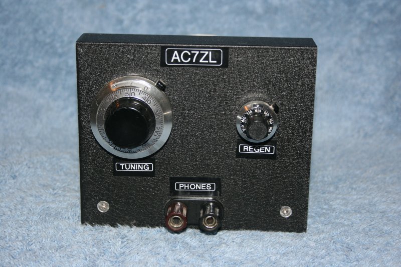
The tuning and reaction controls were fitted with some nice knobs that are really intended for use on 10-turn pots (variable resistors). These knobs not only indicate angular position, but count revolutions as well. They also feature little brake levers which allow the knob to be locked in the desired position. They're normally very expensive items, and gross overkill for this application. As salvage items, however, they were essentially free and lend a nice, clean appearance to the front of the radio.
The Output Transformer
The type and purpose of transformer T1 deserves some explanation. Originally, the Pipsqueak design did not call for an output transformer. The headphone binding posts where connected where the transformer primary now exists.
At one point, during testing, one of my headphone wires came loose. This was the wire that had been attached to the binding post hooked to L3. The wire dangled for second, and then came into contact with the grounded chassis of the radio. Since the other headphone lead was still connected to its binding post, and that post ran back to the plus side of the "B" supply, the net effect of this accident was to apply the full 45 volts of the "B" battery directly across the headphones. This did not hurt the phones, but it did cause them to click so loudly that my ears rang! I was determined that this should not happen again.
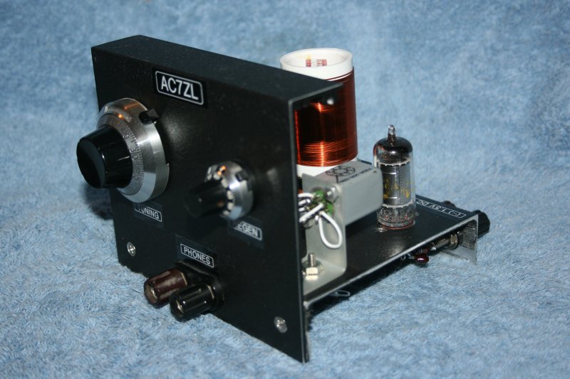
The output transformer is the small, gray cube, just in front of the vacuum tube.
Ideally, T1 should be an audio output transformer that correctly matches the output impedance of the 1T4 tube to the high-impedance headphones I am using. Small vacuum tube audio output transformers are difficult to come by these days, and in any event, I preferred to make due with something in my junk box... after all, that was the whole point of this exercise. There, I discovered a small 115 volt to 12 volt power transformer. I connected the 115 volt primary of the transformer to L3 and the "B" supply, and connected the 12 volt secondary to the headphone binding posts. The presence of the transformer in the headphone circuit not only eliminates the potential for the accident I described a moment ago, it also eliminates all direct current in the headphones. This is a good thing when working with vintage headphones, as it protects them against accidental demagnetization.
Granted, using a power transformer as an audio output transformer is crude, and the electrical match is poor, but I was not able to detect any significant reduction in output volume.
Miscellaneous Parts
The Pipsqueak contains a handful of capacitors, resistors, and other parts of various types and values. None of these are critical in nature, and all them were carefully removed from electronic junk that others had discarded. Substitution with similar parts with ballpark values is not likely to have significant impact on the functionality of the radio.
A Tuning Coil For the AM Broadcast Band
Years ago, radio part manufacturers sold tuning coils that were wound on plastic or bakelite forms. These forms were fitted with metal pins, not unlike a vacuum tube, which allowed the coils to be plugged into sockets. When used in conjunction with the recommended variable capacitor, one of these standard coils could be used to build a radio that tuned across a specific portion of the radio spectrum. Being socketed, it was a simple matter to unplug the coil and replace it with a different type, to allow receiver "coverage" of frequencies not reachable with the first coil. Manufacturers even sold empty or blank coil forms, which allowed experimenters to wind and create their own coils.
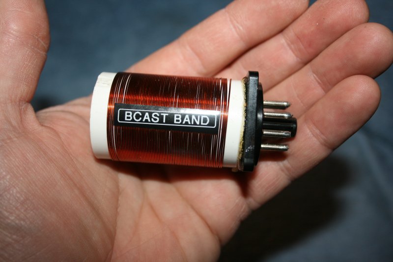
A tuning coil suitable for receiving the A.M. broadcast band.
Unfortunately, neither the coils, nor the blank forms, are available anymore. Desiring a plug-in coil architecture for the Pipsqueak, I endeavored to create my own.
The Pipsqueak coil socket is a standard 8-pin or "octal" socket. These are among the most common sockets still available. Though vacuum tubes have become passe, octal sockets are still widely used in industry to accommodate octal-based plug-in relays.
These relays, by the way, are electromechanical in nature, and eventually wear out. Typically, they are discarded when they become defective. I was given several defective octal-based relays, and decided their bases could be salvaged and used to make plug in coils.
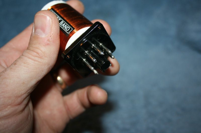
The tuning coil's plug was salvaged from an old plug-in relay.
The first coil I fashioned was for receiving the AM broadcast band. I wound 68 turns of #24 magnet wire on a 1-inch PVC plastic pipe coupler. This would correspond to L1 in the schematic. Next, I wound 16 turns of #24 magnet wire on a short length of 1/2-inch PVC pipe, which became L2. Coil L2 was installed inside of the L1. The coil leads were soldered to the relay plug pins, according to the schematic.

Closing any of these switches increases the capacitance in the tuning circuit, which allows the coil to cover more the A.M. band than it would, otherwise.
The coil, as designed, only covered half of the AM broadcast band. While I could have manufactured a second plug-in coil, designed to pick up where the other coil left off, I decided to try something else. I added a DIP switch which, when closed, adds another variable capacitor to the tuning circuit. This lowers the frequency at which the coil operates.
When I was satisfied that the coil worked the way I desired, I glued the PVC components to the relay base with polyurethane glue. Epoxy adhesive works even better.
A Shortwave Tuning Coil
I have experimented with the construction of other coils in the Pipsqueak, primarily for use at shortwave frequencies. At shortwave frequencies, single-layer coils can pose problems because of the parasitic capacitance that is present between adjacent windings. While techniques can be used to introduce space between windings, I've had good luck with so-called "spiderweb" coils, because the way in which they are wound reduces this parasitic effect. I had never seen anyone use spiderweb coils in a plug-in format, but I figured I give it a shake.
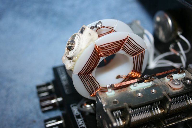
This is a shortwave tuning coil utilizing "spiderweb" windings for reduced self-capacitance. Winding L1 is visible here.
I began with an empty plastic spool, of the type commonly used to dispense Teflon tape or solder. Using an inkpen, I marked the flanges of the spool with seven radial lines. Then, using a hacksaw and these lines as guides, I cut seven radial slots in each flange. One can choose to cut more or fewer slots, but in order for the coils to wind properly, the number of slots must be odd.
I chose one of the flanges, and began winding a coil. The #24 magnet wire was started in one the slots, and then, as the spool was rotated, the wire wire directed through the slots, first inward, then outward. Overall, the exercise is not unlike weaving. I stopped when I had accumulate 8 turns. This coil represents L1, the tuning coil.
I repeated this process on the other flange, but only laid down 4 turns. This smaller coil represents L2, the tickler coil.
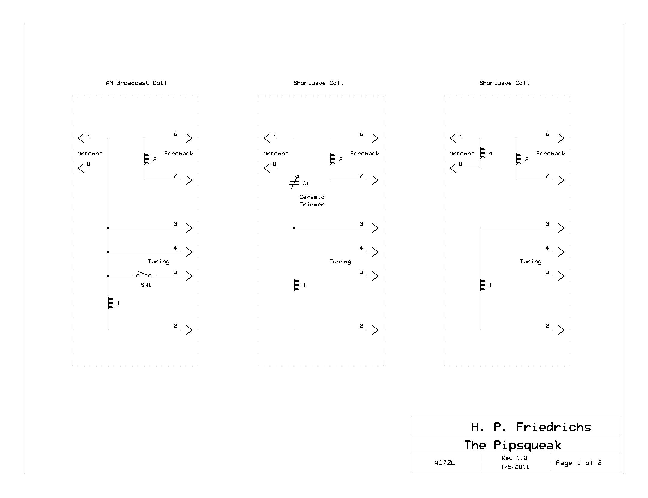
This shows some wiring alternatives in the construction of plug-in coils. Click on the image for better resolution.
The manner in which this plug-in coil was wired can be seen here. Note the addition of a small trimmer capacitor in series with the antenna terminal. This is used to decouple the antenna from the tuning circuit. Sometimes the electrical attributes of an antenna can prevent a regenerative set from functioning properly. The trimmer capacitor is intended to minimize this possibility.
Once experimentation with the shortwave coil was complete and the coil was known to be functional, I glued the coil components together to form a solid, plug-in unit.
Final Thoughts
The Pipsqueak works well, particularly given its simplicity. It's easy to tune, and the regeneration control is well behaved. I have connected it to a variety of wire antennas, without problem.
The design of plug-in coils for this set, as with any regenerative radio, is largely a matter of trial-and-error, but the manner in which the coil socket has been wired offers many options. To build a coil, one must first decide what portion of the HF spectrum the radio should tune. The resonant frequency of the tuning circuit is prescribed by the classic formula:
frequency=1/(2 * PI * SQRT(L*C))
It is true that for any given frequency, there exists an infinite number of combinations of inductance and capacitance that satisfy the equation. However, it is generally accepted that the higher the ratio of L to C, the more selective the tuner. It is best, then, to go for the lower capacitance values.
That said, if the smaller-capacity sections of the variable cap are used, the tuner will exhibit less of a span when in use. In addition, because of the small size of the Pipsqueak, there is little room for large coils. These factors argue for using more capacitance. Note that the amount of variable capacitance utilized by the tuning coil can be varied by making use of some or all of pins #3, #4, and #5 of the coil socket. In any event, once the amount of capacitance has been chosen, the required inductance for tuner can be calculated with the formula.
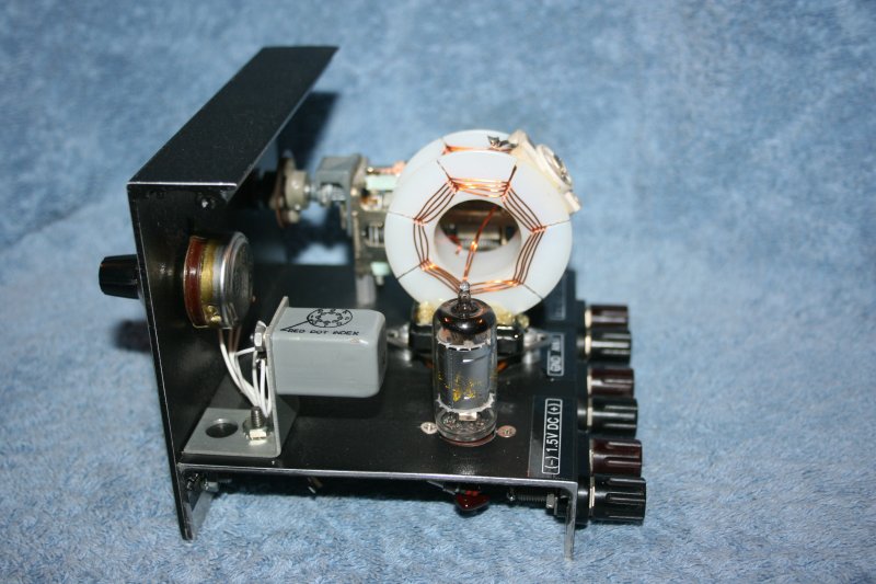
The Pipsqueak receiver with the shortwave coil in place. The tickler winding (L2) is visible.
My experience with tickler coil (L2) winding is that the process involves some voodoo. More turns and placement to the L1 increases the coupling, and therefore, the ability of the set to regenerate. Too much regeneration, however, will make the radio scream, and actually degrades the sensitivity of the set. For any given plug-in, I like to use just enough tickler windings to assure regeneration with the regeneration control set to 3/4 maximum. Your mileage may vary.
There are alternate ways of wiring up the plug-in coil, and options with regard to the way the antenna is coupled to the tuner. Note that the antenna can be connected directly, through a trimmer capactor, or through its own coil or "link" winding.
If you attempt to replicate this set, and find that regeneration does not occur, you may have a problem with the phasing of your coils. This is simple to correct. Disconnect the tickler coil, swap its terminals, and reconnect them.
Another way to modify the Pipsqueak's performance is to tinker with the supply voltages. The radio was designed for a "B" battery supply of 45 volts. "B" voltages up to 90 volts are permissible. The higher voltage seems to result in more volume in the headphones. It also increases the set's tendency to regenerate.
The "A" battery supply, which lights the filament, should never be increased. You'll destroy the tube if you do. On the other hand, I have noticed that a slight decrease in filament voltage can sometimes make weak signals more intelligible. Another trick is to reverse the polarity of the "A" supply.
Document Revision 1, 01/15/2011