H. P. Friedrichs (AC7ZL) Homepage


Radio Room
Building A Mechanical Magic Eye
The Magic Eye Tube
If you're less than 50 years of age, and you don't tinker with vintage radios or antique test equipment, you're probably unfamiliar with the magic-eye tube. Pity, because you've missed out on seeing one of the neatest display devices ever produced. Back in the 1930's, radio manufacturers were interested in providing consumers with a tuning indicator, something that would indicate relative signal strength. Magic-eye tubes were conceived as an alternative to then-expensive and difficult-to-manufacture meter movements.
The magic-eye tube is a cathode ray tube, a cousin to the more sophisticated picture tubes found in television sets and computer monitors. Shapes and styles have varied over the years, but the most common tubes had a small circular screen with a dark round electrode at its center. Electrons, emitted from beneath the center electrode, played onto the screen causing it to glow a rich, hypnotic green color. In viewing the tube in operation, one gets the impression that one is staring into the all-seeing eye of some strange beast, hence the name of the device.
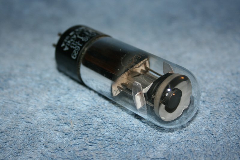
An example of the magic eye tube
Additional electrodes in the tube shaped the beam of electrons striking the screen, resulting in the appearance of one or more glowing "wedges" or "vanes" of light. By varying the signal on the control electrodes, these vanes could be made to expand or contract proportionately. Eye tubes have been used to indicate radio signal strength in receivers, audio levels in tape recorders, and continuity, voltage, and capacitor values in various pieces of test equipment.
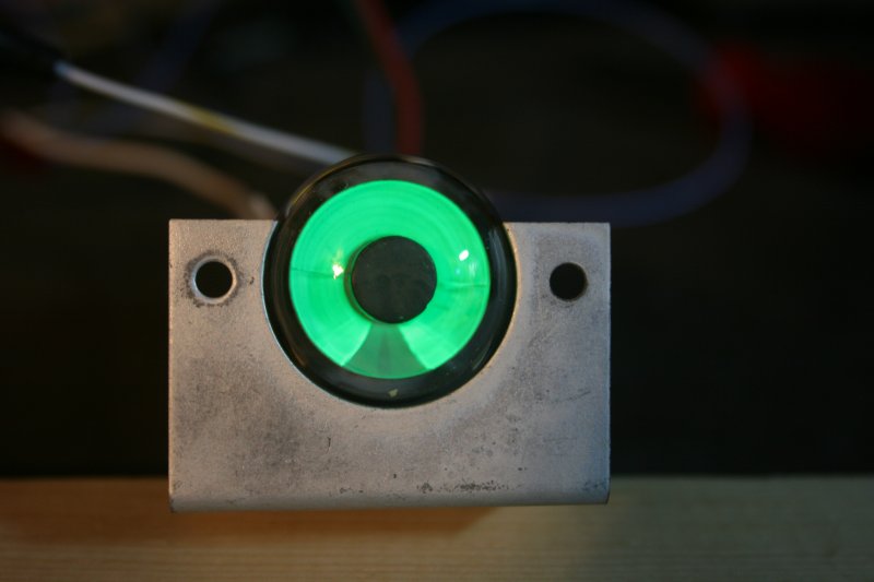
The magic eye tube in operation. Note the glowing "vanes"
Unfortunately, eye tubes have a finite life span, and they have been out of production for many decades. These two facts have conspired to make them rare and difficult to obtain. When samples are found, they often command high prices. In contemplating this situation one afternoon, it occurred to me that it might be possible to fabricate a simple contraption that emulates eye-tube behavior. Besides its intrinsic entertainment value, such a device might prove useful in the restoration of vintage radios in the future, when there are no more eye tubes to be had at any price.
Fooling The Eye
I have long been interested John Logie Baird's mechanical television system, developed in the 1920's. The operation of the system is predicated, in large part, on a biological phenomenon called "persistence of vision." Persistence of vision, or POV, allows a discrete series of frames, displayed in rapid succession, to be perceived as smooth, continuous imagery. Likewise, any light source, moved rapidly enough, will appear to an observer as a continuous streak of light. I hoped to take advantage of this effect to fabricate my eye tube analog.
I envisioned an LED, mounted on the face of a disk, spun by a small electric motor. By turning the LED on and off at precise times during its orbit, I expected to be able to produce an "eye" pattern, complete with expanding and contracting vanes. The trick is to vary the timing of the LED as an input signal varies. As it turns out, I was able to produce an eye tube effect with surprisingly simple electronics, composed entirely of junk-box parts.
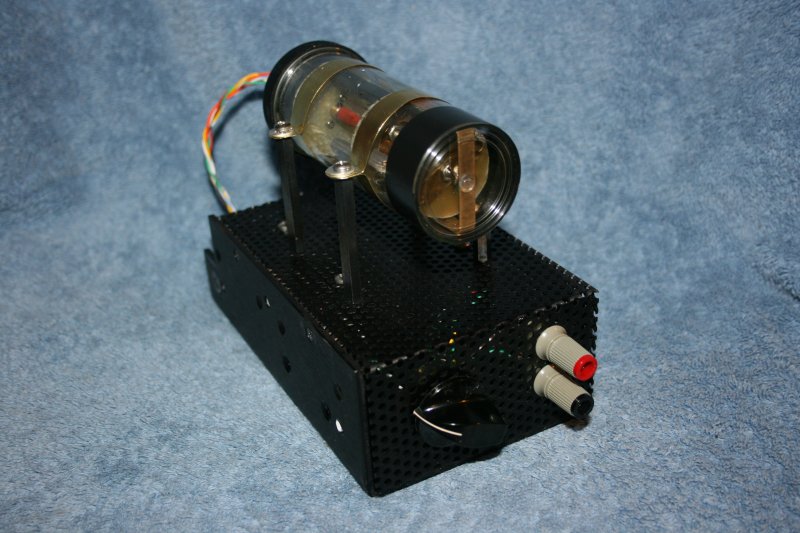
The mechanical magic eye tube prototype
The Circuit
My prototype display consists of two green LEDs, mounted to a rotating disk. For the time being, I'll ask that you disregard the matter of how power is actually delivered through the rotating parts. I'll address that in more detail, shortly.
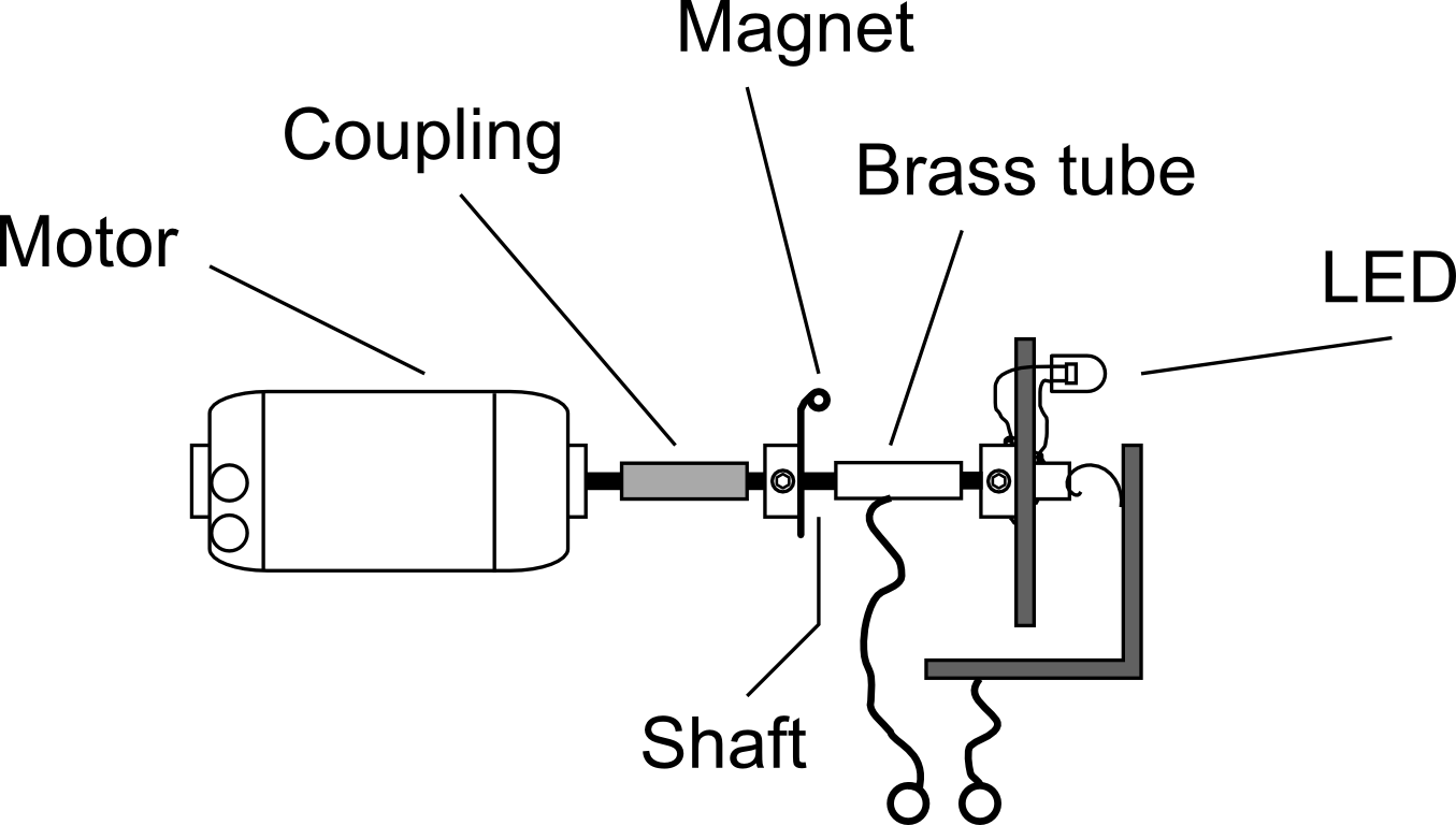
The display disk is attached to a shaft, and that shaft is driven by a small D.C. motor. Since display behavior is dependent on timing, I used an LM7805 (U2) to regulate the voltage feeding the motor. Another LM7805 (U1) is used to regulate power for the rest of the circuitry.
Timing signals are generated with the 1-microfarad capacitor, C6. C6 is charged from the 5-volt supply rail through timing resistor R5. Mounted on the rotating shaft of the display is small magnet which is oriented to whirl past the face of a glass reed switch. Once every revolution of the display disk, the reed switch is closed, and C6 is shorted to ground. This resets it to zero volts, after which it begins to charge up again. If you probe the junction between R5 and C6 with an oscilloscope as the apparatus is running, you will find a signal that looks more or less like a saw tooth.
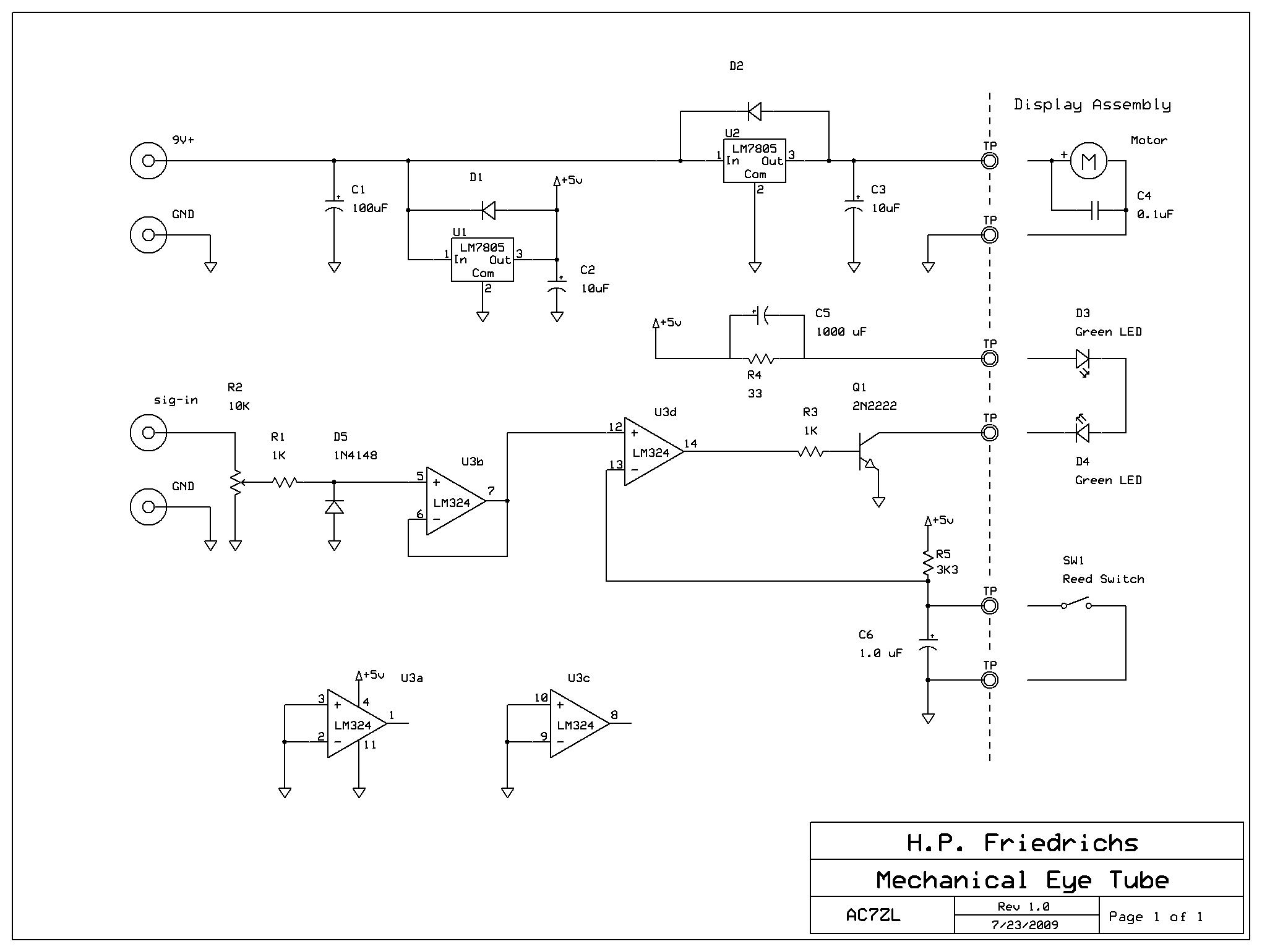
The mechanical magic eye schematic. Click on this image to enlarge it
The control or input signal to the device is attenuated by the 10-kilohm potentiometer R2. A clamp composed of R1 and D5 follow, and are used to protect downstream circuitry from the accidental application of negative voltages. Following the clamp, the signal is buffered by a unity-gain amplifier composed of one amp (U3-b) from an LM324 quad op amp package.
A second amplifier (U3-d), is configured as a comparator. This is used to compare the amplitude of the incoming control signal with the saw tooth produced by R5 and C6. If the output of the comparator goes high, the LEDs in the display are turned on. If the comparator output goes low, the LEDs are turned off. R3 limits drive current into the 2N2222 driver transistor Q1. R4 limits the static LED current.
Now, let's explore the operation of the circuit when everything is in motion. Assume for the moment that the applied input signal is 4 volts, and that the attenuator R2 is in mid-position. Furthermore, let's assume that the reed switch, triggered by the magnet on the display shaft, has just closed and discharged C6. Thus, the voltage on pin 12 of (U3-d) will be 2 volts, and the voltage on pin 13 will be zero. Because the signal on pin 12 is greater than the signal on pin 13, the output of the comparator at pin 14 goes high, which turns on the LEDs.
As time passes, and the display disk rotates, the lit LEDs prescribe an arc of light. Also, as time passes, C6 charges up, and the voltage at pin 13 of (U3-d) will rise. When the voltage on C6 exceeds the input signal voltage, the output of the comparator (U3-d) will go low, turning the LEDs off.
Every rotation, C6 is reset by the reed switch, and so the process repeats.
The apparent length of arc produce by the rotating LEDs depends upon the length of time that the LEDs are actually turned on. The length of time the LEDs are on depends upon the time it takes for C6 to charge up to the level of the control signal. The higher the control signal, the longer it takes C6 to charge up to that level, and the longer the arcs of light produced by the rotating LEDs. Thus, the length of the glowing arcs produced by the display is proportional to the magnitude of the control signal.
Mechanical Details
The mechanical details of my eye tube are as simple and straightforward as the circuitry, though a few comments are in order.
Since the idea of the project was to come up with a replacement for magic eye tubes, I thought the unit should take the basic form of the tube. This suggested a long, cylindrical layout that would be suitable for insertion into some kind of tubular enclosure. I found a clear plastic jar with a screw-on lid that seemed to fit the bill. With the enclosure in hand, the rest of the display components were sized to fit inside.
The display disk is a piece of fiberglass PC board material. Soldered to the disk is a small brass collar fitted with a set screw. This provides an easy way to attach the disk to a rotating shaft. Such collars can be made from scrap, or purchased at hobby stores that carry supplies for radio-controlled airplanes.
Mechanical details
The disk is fitted onto a short length of brass rod, which serves as a drive shaft. A piece of brass tubing forms a bearing in which the shaft may turn. Also on this shaft is brass arm, soldered to a collar with a set screw, to which one may glue a magnet. This is used to actuate the reed switch that periodically resets capacitor C6. An excellent source of tiny but powerful magnets is a dead CDROM drive. If you dissect the tiny mechanism that focuses the laser beam, you'll find one or more pill-sized rare-earth magnets.
Likewise, the motor the drives the display is small permanent magnet motor that was salvaged from the drawer mechanism of a dead CDROM drive. Any number of similar motors will do just as well.
The shaft of the display is coupled to the motor shaft with a piece of rubber tubing. The compliant nature of the rubber tubing will compensate for minor errors in shaft alignment.
The remaining issue is how to deliver power to the rotating LEDs. This is accomplished in two ways. One LED terminal is soldered to the collar on the display disk. Current flows through the collar to the shaft, and through the shaft to the brass tube comprising the bearing. A wire can be soldered to the brass tube.
The second LED terminal is connected to a piece of brass soldered to the front side of the display disk. A curled piece of brass shim stock acts as a brush to pick up current and complete the circuit.
Going Further
I am fond of modification-tolerant designs that can be constructed with scrap and spare parts. There is ample opportunity here for further experimentation and improvement. Before I set you on your way, let me share a few thoughts.
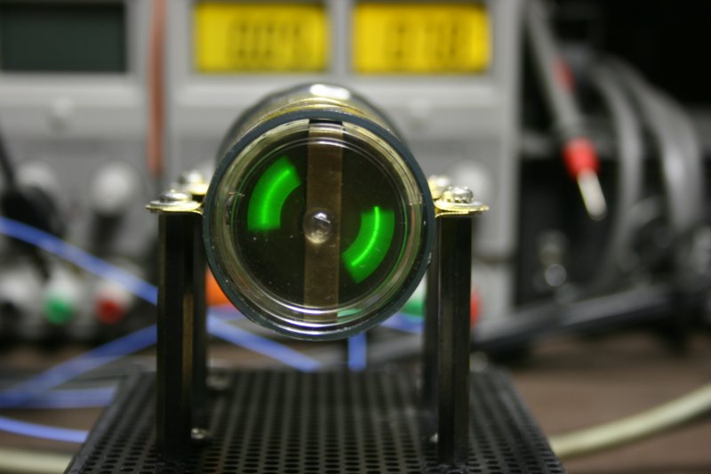
The mechanical magic eye tube in operation
My first prototype was constructed with an old computer CPU fan. There are some challenges with using a motor of this type, but there are also significant advantages. CPU fans are brushless motors that run very quietly. Without brushes, they don't produce sparking that might cause problems if the mechanical eye tube was deployed in an old receiver.
In addition, CPU fan motors often have a speed-output line. This is an open-collector transistor that pulls the speed line to ground a couple of times per revolution of the fan. I have used this signal to directly reset capacitor C6, which eliminates the need for the rotating magnet and reed switch.
Original eye tubes came in different "flavors." Some had one vane that moved, some had two, some had four. You can change the number of vanes produced by the mechanical eye tube by adding more LEDs, or by increasing the number of times that C6 is reset per revolution. Proper operation may require adjustments to R5 and C6.
Spinning the LEDs produces the brightest display, but this approach has the disadvantage that rotating contacts must be employed. A far simpler design is to use a set of fixed LEDs mounted behind a rotating disk that has a view-slot cut into it. I have tried this alternate approach to scanning, and it works well, too.
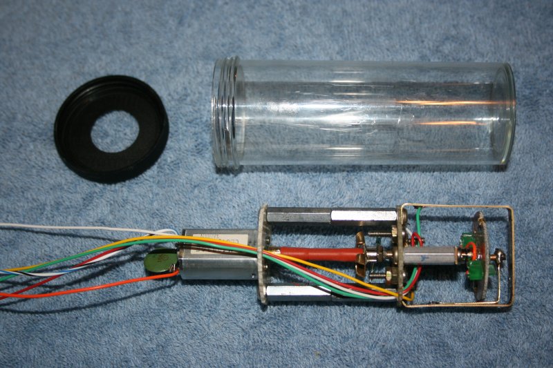
Interior components of the mechanical magic eye tube
It is desirable to drive the LEDs as hard as possible, so as to produce the greatest amount of light. Yet, LEDs are prone to damage if current limits are exceeded. I selected R4 to limit the maximum current to my LEDs to about 17 mA. However, since the LEDs are being flashed on and off, the effective current is always less, and so is the light produced. By bypassing R4 with a large electrolytic capacitor, I could deliver more current to the LEDs when the display disk was spinning, yet still protect them from over-current if the reed switch or comparator should ever fail to turn the LEDs off.
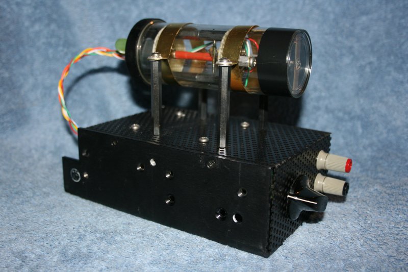
Another view of the prototype
One final thought: Both original eye tubes and my mechanical equivalent are dynamic display devices. It's impossible to do them justice with static photos in the pages of a magazine. For this reason, I invite you to view a short video that I've posted to Youtube that allows you to see these devices in operation. You can visit Youtube and search for my call sign, AC7ZL, or go directly to this URL:
http://www.youtube.com/watch?v=QFTDOZz-LlE
Useful and Interesting Links
|
Philip Rheinschild's magic eye catalog |
|
|
Wiki entry on magic eye tubes |
|
|
Howard's magic eye tube page |
|
|
Educypedia entries for magic eye tubes |
(This article originally appeared in the newsletter of the Xtal Set Society. Check them out!)
Document Revision 1, 01/12/2012