H. P. Friedrichs (AC7ZL) Homepage


Radio Room
Fun With Homebrew Cuprous Oxide Diodes
Note: This article originally appeared in the January 2010 issue of the Xtal Set Society newsletter. The article originally appeared in two parts. It is reproduced here in its entirety.
Introduction To Part One
Several years ago, I invested a fair amount of time tinkering with garden-shed chemistry for the purpose of producing semiconductor junctions for primitive transistors. Part of that work appeared in my book, Instruments of Amplification, the details of which are beyond the limited space here. Suffice it to say that I experimented with the properties of copper and its oxides, and in fabricating devices based on this chemistry, I developed a fairly reliable method for producing robust films of copper oxide. I also discovered that simple semiconductor junctions made from this material make excellent detectors (diodes) for my crystal radio projects.
In Part 1 of this article, I'll share some background on copper oxide, and my own fabrication process. In Part 2, I'll show you how I built a very nice fixture for using the oxides we've produced, and what happened when this device is wired up in a simple radio circuit. Ready? Let's begin.
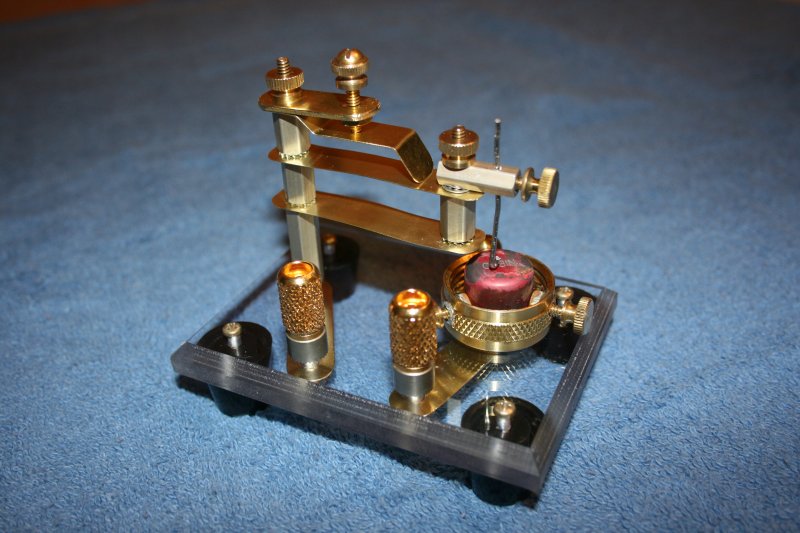
The completed cuprous oxide detector (diode)
Copper and Its Oxides
It goes without saying that copper oxide is composed of copper and oxygen. However, as it turns out, there are two varieties of copper oxide, which differ in the proportion of copper to oxygen in each molecule. The first, cupric oxide, is composed of molecules wherein a single atom of copper is joined with a single atom of oxygen. At room temperatures, this material is a dull, dark or black solid. It is of no interest to us here.
The second variety of copper oxide is called cuprous oxide, and is comprised of molecules containing two atoms of copper joined with a single atom of oxygen. This material is a pretty, dark, salmon color, and is the semiconducting material we shall both produce and exploit in just a moment.
Copper Oxide Rectifiers
In 1927, a fellow by the name of Grondahl was issued United States Patent number 1,640,335 entitled, Unidirectional Current Carrying Device. In other words, he had patented a cuprous oxide diode. Grondahl's work is really geared toward power rectification, i.e., converting alternating current to direct current for power supplies or to charge batteries. None the less, a rectifier is a diode and a diode can be used as a primitive radio detector, it's just the Devil that lies in the details.
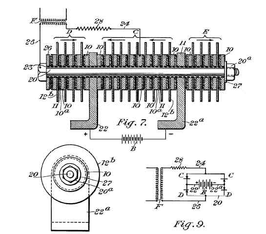
A portion of the Grondahl patent
The magic of the Internet allows anyone to search for and review patents like Grondahl's, so I downloaded a copy. I would urge you to obtain a copy of your own and skim through it, as it fleshes out some of the details that time and space require me to gloss over. Besides, it makes for interesting reading.
Grondahl introduces a round disk or "washer" of pure copper. On top of this copper, he applies or fabricates a layer of cuprous oxide. Stacked upon that is another metallic washer composed of something soft, like lead. This "sandwich" is held in compression with a bolt. The copper washer comprises one terminal of the diode, the lead washer, the other.
Grondahl's patent goes on to describe variations in this construction technique to improve the voltage rating of the device and to effect full-wave rectification by arranging stacks of copper and lead disks into "bridges." None of this is of interest to us but the basics: a copper substrate which forms one terminal of the diode, a layer of cuprous oxide, and a soft, compliant metal contact, pressed against the oxide layer, which comprises the other terminal.
Growing Cuprous Oxide
Growing cuprous oxide involves the use of some chemicals and heat. Thus, I would urge everyone to approach this process in a safe fashion. Do not attempt this without the benefit of goggles to protect the eyes, gloves to protect the hands, and make sure that the work is performed somewhere with adequate ventilation. I would recommend that you read through the process and understand it before starting out, and I would also recommend that interested youngsters take advantage of the guidance of a parent or teacher. If I might be so bold, I would invite you to pick up your own copy of Instruments of Amplification, where my experiments and safety precautions are described in greater detail. In any event, you are responsible for your own safety.
Having said all that, you will need the following materials to make your own cuprous oxide: a clean piece of copper, a small quantity of sodium or potassium hydroxide, and some hydrochloric acid. You'll also need some sodium tetraborate decahydrate. Finally, you'll need a source of high heat like an electric hot plate or a propane torch.
Before you are frightened off by the chemicals I've just listed, consider that in all likelihood, these are already present in your garage, kitchen, or laundry room. Sodium and potassium hydroxides are the active ingredients in lye and drain cleaners, so this material can be found at the local supermarket. Hydrochloric acid, also known as muriatic acid, is used to clean concrete and masonry, as well as to adjust the PH levels in swimming pools. It can be found at hardware stores or at swimming pool supply houses. Finally, sodium tetraborate is known to anyone who does his own laundry, though most likely by its common name, borax.
The first step in producing a good layer of cuprous oxide is to clean the copper thoroughly with soap and water. A synthetic scouring pad can be used to brighten up the metal. Avoid leaving deep scratches and do not use steel wool.
Next, the copper is cleansed of any remaining grease or oils by washing the metal gently in a lye solution. When the metal is clean, it should be rinsed thoroughly in distilled water. From this point forward, the metal should not be handled with the fingers, but with pliers, forceps, or tweezers.
Now, the metal must be heated. Place the copper on the electric hot plate, or use pliers or forceps to suspend it above your propane flame. Note that the combustion products from the propane flame can potentially contaminate the metal, so be careful to heat one side only, or better yet, place the copper on a small plate of steel and heat the steel with the torch. The steel will transfer the heat to the copper more evenly. A stainless steel cover plate for wall-outlet box is ideal. A warning is in order, however. Avoid using galvanized metal as your "hot plate." Galvanized metal is coated in zinc, and high temperature will burn the zinc off. You won't do well to breathe those fumes!
Back to the process. The first heating step must be done with great care and attention, because the copper metal will quickly assume a light bluish hue as it heats up. The instant this color change becomes apparent, the copper must be removed and immersed in a saturated solution of borax.
The borax solution is prepared in advance with distilled water. Add borax to the water and stir until it dissolves. Add more borax, and continue to do so until no more can be induced to dissolve.
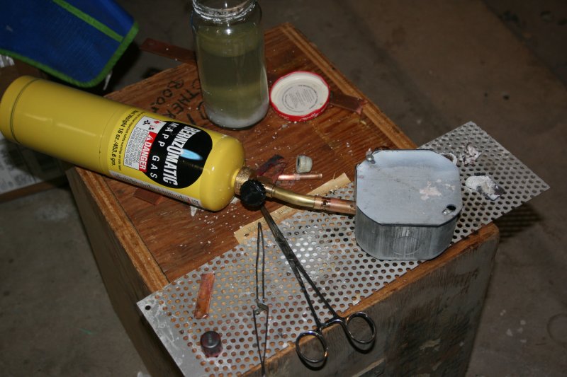
An impromptu hot plate
Remove the copper from borax solution and return it to the hotplate. This time, the copper should be heated until it reaches a dull, red, glow. Maintain the heat for a several minutes, then remove the copper and immerse it in distilled water.
If all has gone well, the copper will be coated with a black layer of cupric oxide. Using forceps, the copper should be dipped in a tumbler of muriatic acid, then removed and swished about in distilled water. Dip the metal back into the acid, and then back into the water. Each time this step is repeated, you will notice that some amount of the black cupric oxide will dissolve away. Repeat as necessary until the black layer is gone, but be careful! Beneath the black lies the salmon-colored cuprous oxide, the material we are really interested in. If you are too aggressive with the acid, you'll eat way both layers and you'll probably have to start all over.
I have read that during the period when cuprous oxide rectifiers were mass produced commercially, the preferred source of copper was Chile. This suggests that there was some trace impurity in Chilean copper that worked to improve or enhance the semiconducting properties of the oxide. It stands to reason, then, that other types of impurities might actually degrade the rectifying properties of cuprous oxide, and I've subsequently found some evidence of this.
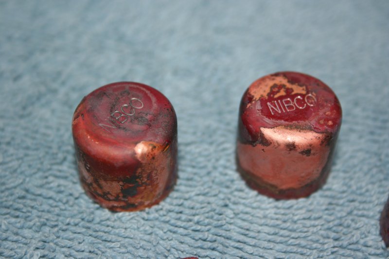
Treated copper pipe caps with cuprous oxide coatings
For mechanical reasons (evident in Part Two), I chose to grow the oxide on small copper pipe caps. After treating the caps as described above and growing beautiful layers of oxide, you can imagine my surprise when they showed no evidence of proper function at all! I tried treating at least a dozen different caps before finding some that finally worked. Why this would be the case I do not know, though I wonder if, given the current high price of copper, manufacturers of "copper" pipe caps have taken the liberty to alloy their copper with something cheaper so as to raise their profit margin. I mention this only to suggest that you exercise care in selecting your copper materials to assure that they are, in fact, pure copper!
Resist the temptation to overheat the copper. It takes a comparatively long time to treat copper when heated to a dull glow, but the resulting oxides have superior properties to those grown quickly at high heat. Bear this in mind if your first attempt at growing oxide layers proves unsuccessful.
I have included patent numbers as references at the end of Part Two of this article. Some of them describe commercial fabrication processes in detail, including specific temperature profiles.
Next time we meet, we will discuss the construction of an instrument to secure and probe our oxide samples, how to use this detector in a simple radio circuit, and some of the strange and interesting behavior you can expect to see.
----------------------------------------------------------------------------------
Introduction To Part 2
In Part One of this article, I introduced you to cuprous oxide as a semiconducting material, described its early application in rectifiers, and I shared with you my process for growing oxide layers on copper using household chemicals.
In this installment, I'd like to show you the construction details of an instrument that allows these oxide layers to be used in a practical fashion, and share with you the results that can be expected from building such a device.
Mechanical Fabrication of the Detector Mechanism
When I first began experimenting with cuprous oxide as a semiconductor, I deposited oxide layers on small strips of copper sheet. An alligator clip provided a sound connection to the substrate. I used a short length of lead solder (wire) to probe the surface of the oxide, and found that I could easily demonstrate semiconductor action. You can do this too, though the construction of a more formal mechanism to secure the substrate and apply the probe in a controlled fashion is very much worthwhile.
My approach is evident in the accompanying photographs. The design is neither new, nor original. It was inspired by and based upon an instrument called a Ferron detector, which was manufactured by Clapp-Eastham in the early 1900's. An example of this appears in Alfred Morgan's classic work, Wireless Telegraph Construction for Amateurs, circa 1913.
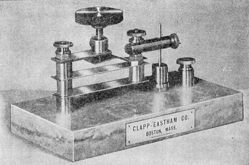
The Clapp Eastham Ferron detector
You will note in the text that follows, that I am somewhat vague in regard to the dimensions of the parts that comprise my detector. This is on purpose. I encourage experimenters to make liberal use of scrap and recycled materials. Thus, the specific materials you have on hand may not match the materials I had. In any event, the size of the mechanism and its parts is not nearly as important as the relationship between the various parts. Thus, you are at complete liberty to scale and substitute as you see fit.
The base of the detector was fashioned from a scrap of polycarbonate plastic. The base measures 3.0 inches by 4.0 inches. Any number of alternate base materials could be pressed into service, including acrylic, wood, or even ceramic tile. The exact dimensions are immaterial. I attached four plastic feet to the bottom of the base to elevate it and to allow me to make electrical connections from the underside.
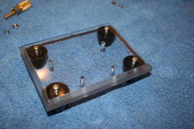
The instrument's polycarbonate base
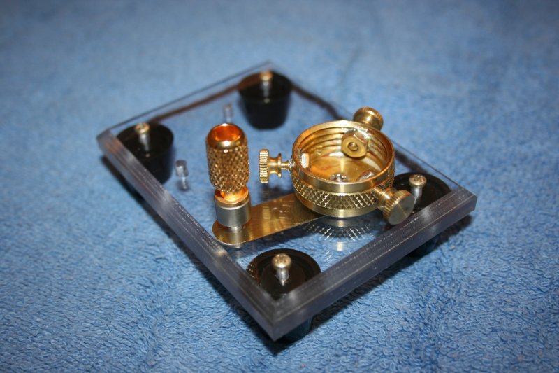
As I mentioned earlier, the cuprous oxide was grown on copper pipe caps. These measure about 0.5 inches. The oxide-laden caps are secured in the detector mechanism in a "sample holder" comprised of a brass cup fitted with three thumbscrews. The cup measures around an inch in diameter, and is ordinarily sold as a means to seal off outdoor water spigots. Around the waist of the cup, I drilled three holes, spaced 120 degrees apart. Inside the cup, aligned with each hole, I soldered a brass nut. From the outside of the cup, through each hole, I installed a thumbscrew. I used 6-32 nuts and screws. I drilled a hole through the floor of the cup so that the sample holder could be bolted to the instrument's base.
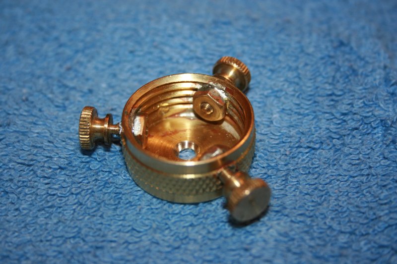
The instrument's "sample holder"
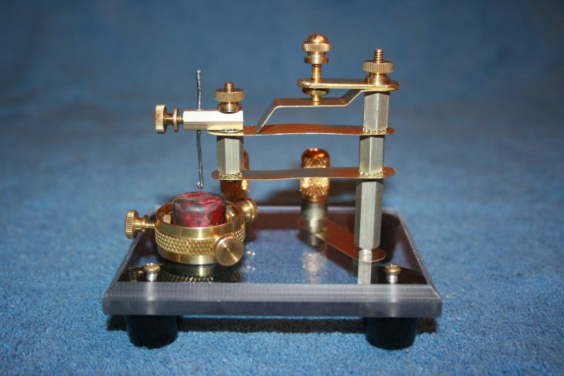
A great deal could be written about the construction and operation of this detector mechanism, but I think I can communicate more than sufficient detail by directing your attention to the photographs and rendering some brief commentary.
The "spine" of the mechanism consists of a stack of hexagonal, aluminum standoffs, threaded onto a length of brass threaded rod. Actually, the threaded rod is a 6-32 rod while the hexagonal standoffs are bored for number 8 threads Thus, the standoffs are loose and can slide along the length of the threaded rod. The spine is secured to the base with an appropriate hex nut, and the stack is held in compression by a knurled thumbnut at the top.
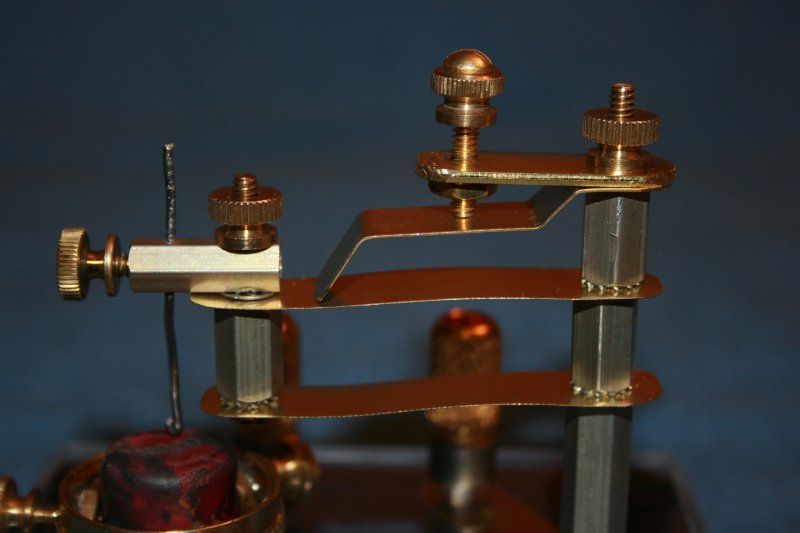
The instrument's mechanism up-close
Extending laterally from the spine are four strips of brass. Each measures a half-inch in width, though their lengths and thickness varies in accordance with their respective function. I made liberal use of star-type lock washers to keep parts aligned when the relevant fasteners are tightened.
The top strip is 1.3 inches long and 0.065 inches thick. I bored two holes in the strip. One hole is sized to accommodate the threaded rod in the spine. The second hole was drilled to clear a 6-32 screw. I aligned a brass hex nut with this hole and soldered it into place. This provides threads for an adjustment screw.
I call the next piece the "transfer strip." It transfers pressure from the adjustment screw to the portion of the mechanism that supports the probe. It measures about 2 inches in length, and 0.018 inches in thickness. It is bent in several places so as to assume the shape of a staircase. The top flat is drilled with a hole to accommodate the threaded rod in the spine. The middle flat is the surface upon which the adjustment screw acts. The tip of the transfer strip applies pressure to the probe support components.
The last two strips are identical to one another. I'll call them "support strips." Each is 2.5 inches in length, and 0.007 inches thick. The choice of thin "shim stock" here allows the strips to flex easily. Each piece is drilled with two holes. One hole accommodates the threaded rod in the spine. The other hold is sized to fit a 6-32 screw at the probe end of the mechanism.
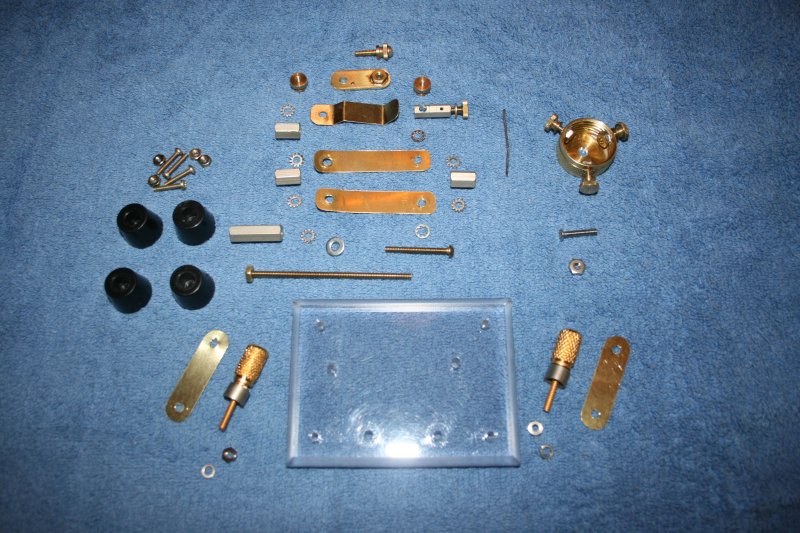
An array of parts, ready for assembly
At the business end of the support strips is a "probe holder." The probe holder is simply another hexagonal standoff. At one end, I drilled a hole through the side of the standoff, sized for a 6-32 screw to provide of means of bolting the probe holder to the support strips. I drilled another hole though the standoff, about 0.065 inches in diameter, to allow of the insertion of a probe wire. Probe wires are locked into place by threading a thumbscrew into axis of the standoff.
Nominally, the probe wire fashioned from a piece of lead solder. I have also used short pieces of steel wire. In the latter case, I use a soldering iron and some solder to create a soft ball of lead at the end of the wire that will contact the oxide.
A backside view of the instrument
How does the mechanism work? The adjustment screw on top applies pressure to the transfer strip. The transfer strip applies pressure to the support strips. Because there are two parallel support strips and because they are bound together with standoffs at each end, they will deflect in such a fashion as to allow vertical motion of the probe, without allowing any lateral motion. The movement of the probe is always parallel to the axis of the spine.
A brass strip makes electrical contact between the binding post and the sample holder
Electrical connections to the detector are made with binding posts. I used strips of thin brass to electrically link one binding post with the detector's spine, and another post to the sample holder.
Use and Observations
I made some attempts to characterize the electrical nature of the oxide films I had grown. It is difficult to draw generalizations, because there was such a range of behavior. Any serious attempt to quantify the specific characteristics of cuprous oxide diodes would have to be prefaced with an effort to secure pure samples of copper (perhaps small cylindrical slugs, turned to the requisite diameter). In addition, it would be important to improve the repeatability of the fabrication process by using a temperature-controlled furnace and reagent-grade chemicals of known pedigree. Having said all this, I can share some anecdotal information that you might find just as useful.
Using an audio signal generator, a 2.2 kilo ohm load resistor, and an oscilloscope set to X-Y mode, I attempted to generate some VI (volt-amp) curves. The curves I observed depart heavily from the ideal. On the plus side, it only takes a few tenths of a volt to drive them into conduction. In terms of sensitivity, this puts them on par with germanium detectors for crystal applications. These are, none the less, leaky devices, and their ability to demodulate A.M. has more to do with simple asymmetry between forward and backward flow than any tendency toward the ideal "brick wall" diode behavior.
I managed to locate some of the junctions that I produced back in 2003, and was pleasantly surprised to find that they still worked. Resistance measurements in the forward and reverse directions showed ratios of 10:1 or greater. The newer pipe-cap-copper junctions didn't fair quite as well, however.
As this entire exercise is really about "homebrew" radio, the real test was whether or not this contrivance would function in a simple receiver set. I have a handy crystal radio tuner that I use for experiments of this type, comprised of a fixed capacitor and a variable inductor. My antenna consisted of about three yards of wire thumb-tacked to the ceiling, and earth ground was provided by the cover plate of a nearby electrical outlet. I wired the detector in series with a set of high-impedance headphones and wired them to the tuner.
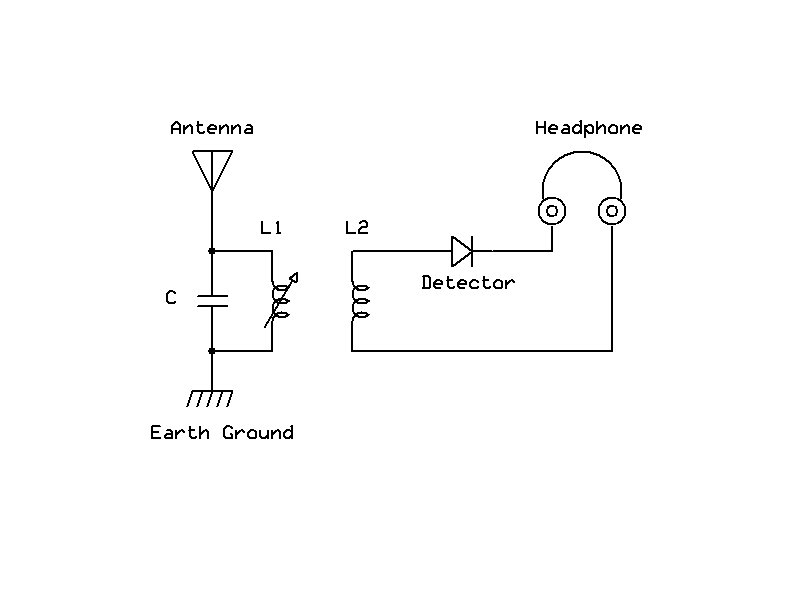
Simplified radio circuit, for details see: http://www.hpfriedrichs.com/rr-cdrom.htm
Using the detector's probe, I searched the cuprous oxide surface of the copper pipe cap until I had found a "sweet spot." Music flooded into my phones. I later replaced the phones with a matching transformer so that I could couple the rig to my desktop computer and make some audio recordings.
On a fluke, I inverted the copper pipe cap and tried probing the oxides that had accumulated in the interior of the cap. These worked much better, and the volume of the audio produced was greatly increased.
I also noticed another peculiarity. The oxide on this particular batch of copper caps works best if moistened (not wet) with water. I have no explanation for this, nor did I observe anything like this when I last experimented with oxide films in 2003. This might be an artifact of the adulterated copper I'm using, or this might trigger some electrolytic action that biases the junction favorably.
Perhaps one of the most interesting things about the cuprous oxide diode is its behavior in response to exposure to light. Mind you, it's not just photosensitive, but photovoltaic. It will actually generate small voltages when light strikes the semiconductor junction.
In recording some audio from my test-bench crystal radio lash-up, I noticed a pronounced "pop" whenever I turned on my bench lamp. Initially, I attributed this to run-of-the-mill electrical noise until I saw the recorded waveform on my computer. The waveform didn't look like those typically generated by impulse noise. Rather, it appeared as though a D.C. offset was suddenly appearing from somewhere. Aha! I remembered that cuprous oxide semiconductors can produce photoelectricity.
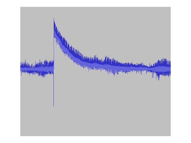
A sudden D.C. offset induced by exposure to light!
I dismantled the radio set-up and connected the detector directly to my digital multimeter. Yes, there was voltage present at the terminals. The voltage difference between the junction lit at ambient levels and the junction illuminated with a bright LED pocket flashlight could be made to vary between 40 and 50 millivolts. Other references I've seen claim that such a junction has the capacity to produce potentials on the order of 250 millivolts. Needless to say, the currents produced are very, very small, so I don't expect to be powering my home with this source of energy any time soon.
Which terminal of the detector is the anode and which the cathode? In Theodore Conti's work, Metallic Rectifiers and Crystal Diodes (1958), Conti identifies the copper substrate as the cathode. This was the basis on which I described the experimental transistor junctions in my own work, Instruments of Amplification, and it's consistent with the images in Grohdahl's patent. When my 2003 junctions are stimulated with light, the substrate becomes the negative terminal of the voltage source.
Curiously, the oxide samples produced for this article, when stimulated with light, act differently. In this case, the substrate becomes positive with respect to the probe. At the moment, I have no explanation for this. Clearly, there is more at play here than meets the eye!
Unanswered questions represent a great opportunity for the curious. However, it is not necessary to solve these puzzles in order to make use of the equipment, especially for radio work.
Conclusion
So there you have it�a functional radio detector built from scraps of metal, hardware, and kitchen chemicals. Not only can it rectify and demodulate, it can produce feeble currents of its own!
Bear in mind that the detector stand described in this article makes an excellent general-purpose fixture for use with natural semiconducting materials like galena or iron pyrite. There are two ways that natural minerals can be installed in the detector.
The first approach is to wrap the mineral sample with a thick layer of aluminum foil, leaving the area to be probed free of foil and accessible. Place the mineral in the sample holder and tighten the thumbscrews. The foil helps to provide a robust electrical connection and, because it's compliant, it will help reduce the chance of the mineral fracturing when under pressure from the thumbscrews.
If you've not yet had your fill of copper pipe caps, they can provide an ideal means of mounting crystals in the detector. Set the cap up like a bowl, fill it either with molten lead or molten Wood's metal, and insert the crystal into the molten liquid. Wait for the metal to solidify, then mount the cap in the sample holder as described earlier. Note that some minerals are damaged by heat, so low-melting-point alloys like Wood's metal are preferable to lead as a mounting medium.
Different detector minerals prefer different kinds of probe wires, and the detector described in this article can easily accommodate whatever you need. Galena seems to prefer phosphor-bronze probes. Phosphor bronze wire can be harvested from the wrappings on larger-gauge acoustic guitar strings (the "E," "A," or "D" strings). With pyrite, I've had luck with music steel. Again, guitar strings are an excellent source of this material. Use the "G," "B," or high "E" strings as necessary.
Interesting Patent Disclosures
| Patent Number |
Title |
Author |
| 1,640,335 |
Unidirectional Current Carrying Device |
O.L. Grondahl |
|
1,924,300 |
Copper Oxide Rectifier |
Alfred L. Atherton |
| 2,205,263 |
Copper Oxide Rectifier |
Carl C. Hein |
|
2,793,968 |
Method of Making Copper Oxide Rectifier Cells |
William Irby |
References
Conti, Theodore, Metallic Rectifiers and Crystal Diodes, copyright 1958, John F. Rider Publisher, Inc., New York
Friedrichs, H.P., Instruments of Amplification, copyright 2003, Published by H.P. Friedrichs, ISBN 0-9671905-1-7
Morgan, Alfred Powell, Wireless Telegraph Construction for Amateurs, copyright 1913, D. Van Nostrand Company
Document Revision 1, 03/04/2010